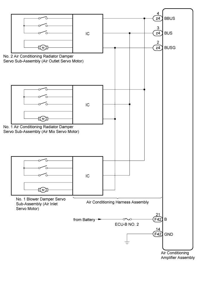
DTC B1497/97 BUS IC Communication Malfunction |
| DTC No. | DTC Detection Condition | Trouble Area |
| B1497/97 | An open circuit or malfunction in the communication line. |
|
| 1.CHECK HARNESS AND CONNECTOR (AIR CONDITIONING AMPLIFIER ASSEMBLY - BATTERY AND BODY GROUND) |
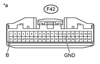 |
Disconnect the F42 air conditioning amplifier assembly connector.
Measure the voltage according to the value(s) in the table below.
| Tester Condition | Condition | Specified Condition |
| F42-21 (B) - Body ground | Always | 11 to 14 V |
Measure the resistance according to the value(s) in the table below.
| Tester Condition | Condition | Specified Condition |
| F42-14 (GND) - Body ground | Always | Below 1 Ω |
| *a | Rear view of wire harness connector (to Air Conditioning Amplifier Assembly) |
|
| ||||
| OK | |
 |
| 2.CHECK AIR CONDITIONING AMPLIFIER ASSEMBLY |
Reconnect the air conditioning amplifier assembly connector.
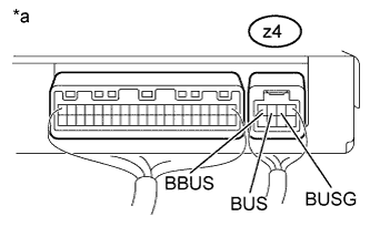 |
Remove the air conditioning amplifier assembly with its connectors still connected (Click here).
Measure the resistance according to the value(s) in the table below.
| Tester Connection | Condition | Specified Condition |
| z4-2 (BUSG) - Body ground | Always | Below 1 Ω |
Measure the voltage according to the value(s) in the table below.
| Tester Connection | Switch Condition | Specified Condition |
| z4-4 (BBUS) - z4-2 (BUSG) | Ignition switch ON | 11 to 14 V |
| z4-3 (BUS) - z4-2 (BUSG) | Ignition switch ON | Pulse generation |
| *a | Component with harness connected (Air Conditioning Amplifier Assembly) |
| Result | Proceed to |
| OK (When troubleshooting according to the DTC) | A |
| OK (When troubleshooting according to Problem Symptoms Table) | B |
| NG | C |
|
| ||||
|
| ||||
| A | ||
 | ||
| ||
