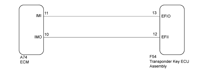
ENGINE IMMOBILISER SYSTEM > Engine does not Start but Initial Combustion Occurs |
| 1.CHECK FOR DTC |
Check for DTCs (Click here).
| Result | Proceed to |
| No DTC output | A |
| DTC output | B |
|
| ||||
| A | |
 |
| 2.READ VALUE USING INTELLIGENT TESTER |
Turn the ignition switch off.
Connect the intelligent tester to the DLC3.
Turn the ignition switch to ON.
Turn the intelligent tester on.
Enter the following menus: Powertrain / Engine and ECT / Data List.
| Tester Display | Measurement Item/Range | Normal Condition | Diagnostic Note |
| Immobiliser Fuel Cut | Status of immobiliser fuel cut/ OFF or ON | - | - |
| Result | Proceed to |
| NG | A |
| OK (for 2NZ-FE) | B |
| OK (for 1NZ-FE) | C |
|
| ||||
|
| ||||
| A | |
|
| 3.CHECK WHETHER ENGINE STARTS |
It leaves for 5 seconds by the ignition switch ON status, and the engine starting operation is done.
| Result | Proceed to |
| Engine cannot be started | A |
| Engine can be started | B |
|
| ||||
| A | |
|
| 4.CHECK ECM (TERMINAL IMI) |
Using an oscilloscope, check the waveform.
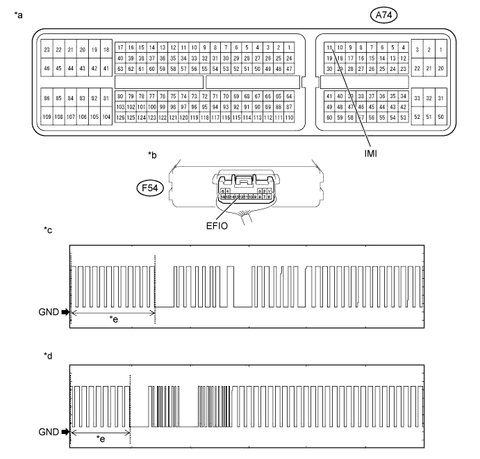
| *a | Component with harness connected (ECM) | *b | Component with harness connected (Transponder Key ECU Assembly) |
| *c | Waveform 1 | *d | Waveform 2 |
| *e | Waveform A | - | - |
| Item | Content |
| Tester Connection | A74-11 (IMI) - F54-13 (EFIO) |
| Tool Setting | 2 V/DIV., 500 ms./DIV. |
| Condition | Within 3 seconds after starter operates and initial combustion occurs, or within 3 seconds after ignition switch first turned to ON after battery disconnected and connected. |
| Result | Proceed to |
| Normal waveform | A |
| Waveform 1 or 2 (Waveform A) not output, or has abnormal wavelength or shape | B |
|
| ||||
| A | |
|
| 5.CHECK ECM (TERMINAL IMO) |
Using an oscilloscope, check the waveform.
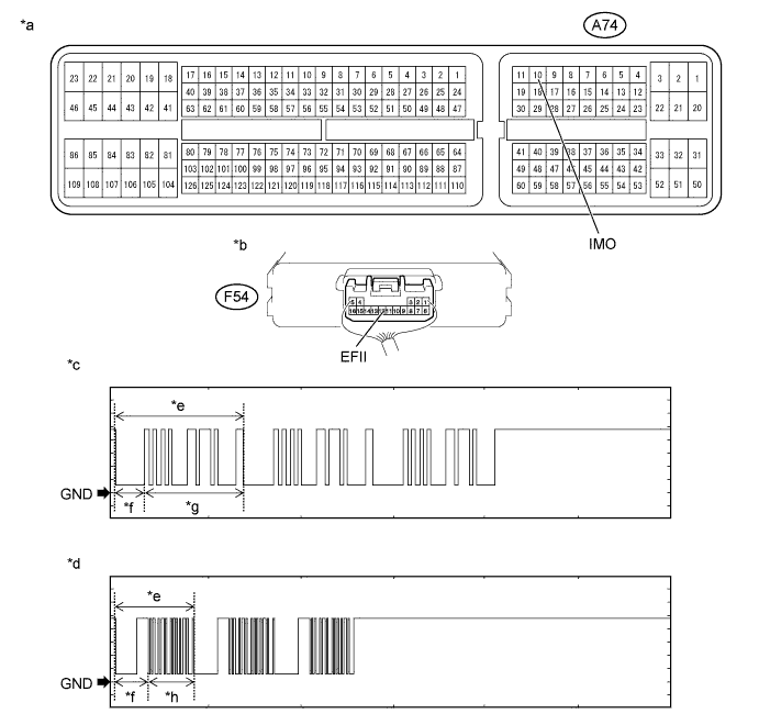
| *a | Component with harness connected (ECM) | *b | Component with harness connected (Transponder Key ECU Assembly) |
| *c | Waveform 1 | *d | Waveform 2 |
| *e | Waveform B | *f | 160 ms |
| *g | 510 ms | *h | 270 ms |
| Item | Content |
| Tester Connection | A74-10 (IMO) - F54-12 (EFII) |
| Tool Setting | 2 V/DIV., 500 ms./DIV. |
| Condition | Within 3 seconds after starter operates and initial combustion occurs, or within 3 seconds after ignition switch first turned to ON after battery disconnected and connected. |
| Result | Proceed to |
| Normal waveform | A |
| Waveform 1 or 2 (Waveform B) not output, or has abnormal wavelength or shape (for 2NZ-FE) | B |
| Waveform 1 or 2 (Waveform B) not output, or has abnormal wavelength or shape (for 1NZ-FE) | C |
|
| ||||
|
| ||||
| A | |
|
| 6.CHECK ECM (TERMINAL IMI) |
Using an oscilloscope, check the waveform.
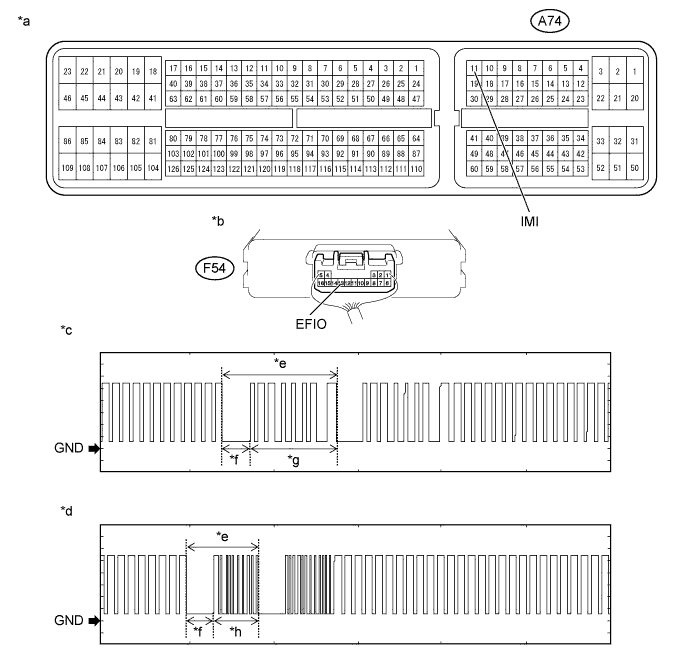
| *a | Component with harness connected (ECM) | *b | Component with harness connected (Transponder Key ECU Assembly) |
| *c | Waveform 1 | *d | Waveform 2 |
| *e | Waveform C | *f | 160 ms |
| *g | 510 ms | *h | 270 ms |
| Item | Content |
| Tester Connection | A74-11 (IMI) - F54-13 (EFIO) |
| Tool Setting | 2 V/DIV., 500 ms./DIV. |
| Condition | Within 3 seconds after starter operates and initial combustion occurs, or within 3 seconds after ignition switch first turned to ON after battery disconnected and connected. |
| Result | Proceed to |
| Normal waveform | A |
| Waveform 1 or 2 (Waveform C) not output, or has abnormal wavelength or shape | B |
|
| ||||
| A | |
|
| 7.REGISTER ECU COMMUNICATION ID |
Reregister the ECU communication ID (Refer to Service Bulletin).
| NEXT | |
|
| 8.CHECK WHETHER ENGINE STARTS |
Check that the engine starts with the key.
|
| ||||
| OK | ||
 | ||
| ||
| 9.CHECK HARNESS AND CONNECTOR (ECM - TRANSPONDER KEY ECU ASSEMBLY) |
Disconnect the A74 ECM connector.
Disconnect the F54 transponder key ECU assembly connector.
Measure the resistance according to the value(s) in the table below.
| Tester Connection | Condition | Specified Condition |
| A74-11 (IMI) - F54-13 (EFIO) | Always | Below 1 Ω |
| F54-13 (EFIO) - Body ground | Always | 10 kΩ or higher |
|
| ||||
| OK | |
|
| 10.REPLACE TRANSPONDER KEY ECU ASSEMBLY |
Replace the transponder key ECU assembly with a new one (Refer to Service Bulletin).
Check that the engine starts with the key.
| Result | Proceed to |
| OK | A |
| NG (for 2NZ-FE) | B |
| NG (for 1NZ-FE) | C |
|
| ||||
|
| ||||
| A | ||
| ||
| ||

