ASSEMBLY
HOUSING-AIR DISTRIBUTION
NOTE: The air distribution housing must be removed from the HVAC housing and disassembled for service of the mode-air and blend-air doors.
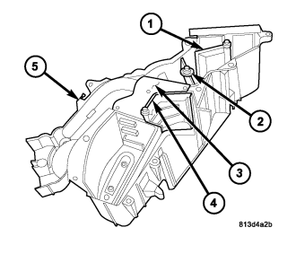
1. Install the upper defrost/panel-air door (1), lower defrost/panel-air door (2), directional vane (3) and the blend-air door (4) into the left side air distribution housing (5) as required. Align the air doors with the pivot shaft holes in the housing.
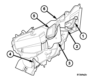
2. Install the upper defrost/panel-air door (1), lower defrost/panel-air door (2), directional vane (3), rear outlet-air door (4) and the blend-air door (5) into the right side air distribution housing (6) as required. Align the air doors with the pivot shaft holes in the housing.
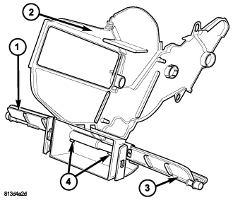
3. If removed, align the front floor-air doors (1 and 3) with each other and install then into the center partition (2). Make sure that the air door retaining tabs (4) are fully engaged.
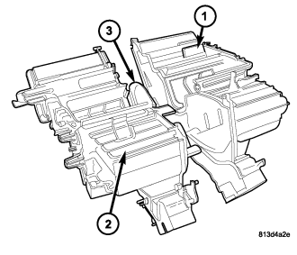
4. Install the center partition (3) into the right half of the air distribution housing (2).
5. Install the left half of the air distribution housing (1) onto the right half of the air distribution housing. Align the air door pivot shafts with each other and with the pivot shaft holes in the housing.
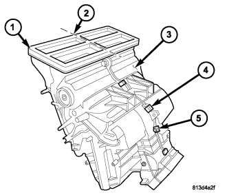
6. Install the eight screws (5) that secure the two halves of the air distribution housing (3) together. Tighten the screws to 2.2 N·m (20 in. lbs.).
7. Install the four metal clips (4) that secure the two halves of the air distribution housing together.
8. Inspect the foam seal (1), especially at the parting line (2). If the seal is deformed or damaged, it must be replaced.
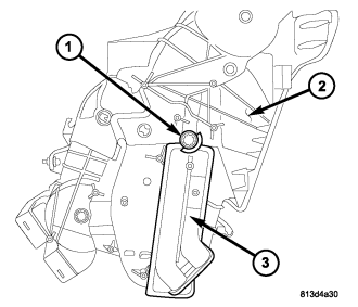
9. On LHD models, carefully install the heater core (3) into the right side of the air distribution housing (2).
10. If equipped with dual zone heating-A/C, install the blend door stop (1) onto the right side of the air distribution housing.
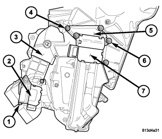
11. Position the rear floor/console door actuator (2) onto the right side of the air distribution housing (3). If necessary, rotate the actuator slightly to align the splines on the actuator output shaft with those on the floor/console door pivot shaft (refer to 24 - HEATING & AIR CONDITIONING/CONTROLS - FRONT/ACTUATOR-MODE DOOR - INSTALLATION).
12. Install the screws (1) that secure the rear floor/console door actuator onto the right side of the air distribution housing. Tighten the screws to 2 N·m (17 in. lbs.).
13. If equipped with dual zone heating-A/C, position the blend door actuator mounting bracket (5) onto the right side of the air distribution housing and install the retaining screws (4). Tighten the screws to 2 N·m (17 in. lbs.).
14. If equipped with dual zone heating-A/C, position the blend door actuator (7) onto the blend door actuator mounting bracket and install the retaining screws (6). Tighten the screws to 2 N·m (17 in. lbs.). If necessary, rotate the actuator slightly to align the splines on the actuator output shaft with those on the blend door stop (refer to 24 - HEATING & AIR CONDITIONING/CONTROLS - FRONT/ACTUATOR-BLEND DOOR - INSTALLATION).
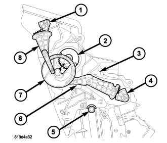
15. On RHD models, carefully install the heater core into the left side of the air distribution housing (3).
16. Install the front floor door linkage rod (6) and the lower defrost/panel door pivot gear (2) onto the left side of the air distribution housing.
NOTE: Align the arrow on the lower defrost/panel door pivot gear with the locator in the window of the mode door cam during installation of the mode door cam.
17. Align and install the mode door cam (7) onto the left side of the air distribution housing.
NOTE: Align the guide pin on the upper defrost/panel door linkage rod with the guides in the mode door cam during installation of the upper defrost/panel door linkage rod.
18. Align and install the upper defrost/panel door linkage rod (8) onto the left side of the air distribution housing.
NOTE: Align the detent in the upper defrost/panel door pivot gear with the locator in the upper defrost/panel door linkage rod during installation of the upper defrost/panel door pivot gear.
19. Align and install the blend door stop (5), front floor door pivot gear (4) and the upper defrost/panel door pivot gear (1) onto the left side of the air distribution housing.
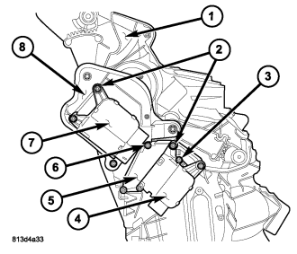
20. Position the blend door actuator mounting bracket (5) and the mode door actuator mounting bracket (8) onto the left side of the air distribution housing (1) and install the retaining screws (3 and 6). Tighten the screws to 2 N·m (17 in. lbs.).
21. Position the blend door actuator (4) and the mode door actuator (7) onto the mounting brackets and install the retaining screws (2). Tighten the screws to 2 N·m (17 in. lbs.). If necessary, rotate the actuators slightly to align the splines on the actuator output shaft with those on the mode door cam and the blend door stop (refer to 24 - HEATING & AIR CONDITIONING/CONTROLS - FRONT/ACTUATOR-BLEND DOOR - INSTALLATION) and (refer to 24 - HEATING & AIR CONDITIONING/CONTROLS - FRONT/ACTUATOR-MODE DOOR - INSTALLATION).
22. Install the air distribution housing onto the HVAC housing (refer to 24 - HEATING & AIR CONDITIONING/DISTRIBUTION - FRONT/HOUSING-HVAC - AIR DISTRIBUTION HOUSING - INSTALLATION).
HOUSING-AIR INLET
NOTE: The air inlet housing must be removed from HVAC housing and disassembled for service of the recirculation-air door.
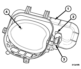
NOTE: LHD model shown. RHD model similar.
1. Position the recirculation-air door (4) into the air inlet housing (1).
CAUTION: Make sure that the recirculation-air door pivot shaft is properly seated in the pivot seats located on the air inlet housing.
2. Install the recirculation door actuator (3) onto the air inlet housing. If necessary, rotate the actuator slightly to align the splines on the actuator output shaft with those on the recirculation door pivot shaft (refer to 24 - HEATING & AIR CONDITIONING/CONTROLS - FRONT/ACTUATOR-RECIRCULATION DOOR - INSTALLATION).
3. Install the two screws (2) that secure the recirculation door actuator to the air inlet housing. Tighten the screws to 2 N·m (17 in. lbs.).
4. Install the air inlet housing onto the HVAC housing (refer to 24 - HEATING & AIR CONDITIONING/DISTRIBUTION - FRONT/HOUSING-HVAC - AIR INLET HOUSING - INSTALLATION).
HOUSING-HVAC ASSEMBLY
CAUTION: Be certain to adjust the refrigerant oil level when servicing the A/C refrigerant system (refer to 24 - HEATING & AIR CONDITIONING/PLUMBING - FRONT/REFRIGERANT OIL - STANDARD PROCEDURE - REFRIGERANT OIL LEVEL). Failure to properly adjust the refrigerant oil level will prevent the A/C system from operating as designed and can cause serious A/C compressor damage.
NOTE: When replacing multiple A/C system components, refer to the Refrigerant Oil Capacities chart to determine how much oil should be added to the refrigerant system (refer to 24 - HEATING & AIR CONDITIONING/PLUMBING - FRONT/REFRIGERANT OIL - STANDARD PROCEDURE - REFRIGERANT OIL LEVEL).
NOTE: If the A/C evaporator is being replaced, add 60 milliliters (2 fluid ounces) of refrigerant oil to the refrigerant system. Use only refrigerant oil of the type recommended for the A/C compressor in the vehicle.
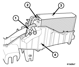
1. If removed, install the insulator (3) over the A/C evaporator (2). If the seal is deformed or damaged, it must be replaced.
2. If removed, install the rubber seal (1) into the lower half of the HVAC housing (4). If the seal is deformed or damaged, it must be replaced.
3. Install the A/C evaporator into the lower half of the HVAC housing. Make sure that the evaporator drain within the HVAC housing is clean and unrestricted and that the insulator and rubber seal are properly installed.
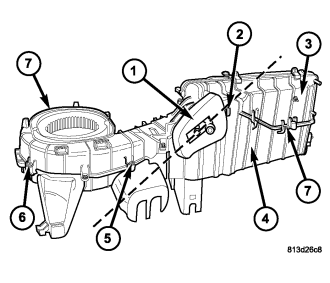
4. Install the upper half of the HVAC housing (3) onto the lower half of the HVAC housing (4) and fully engage the two plastic retaining clips (7).
5. Install the ten screws (6) that secure the two halves of the HVAC housing together. Tighten the screws to 2.2 N·m (20 in lbs.).
6. Install the three metal retaining clips (5) that secure the two halves of the HVAC housing together.
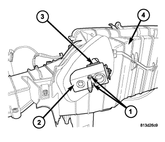
7. Remove the tape or plugs from the evaporator tube fittings and all of the expansion valve ports.
8. Lubricate new rubber O-ring seals with clean refrigerant oil and install them on the evaporator tube fittings. Use only the specified O-rings as they are made of a special material for the R-134a system. Use only refrigerant oil of the type recommended for the A/C compressor in the vehicle.
9. Install the A/C expansion valve (2) onto the evaporator tube tapping block (3) located at the front of the HVAC housing (4).
10. Install the two bolts (1) that secure the A/C expansion valve to the evaporator tube tapping block. Tighten the bolts to 11 N·m (97 in. lbs.).
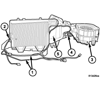
11. Install the evaporator temperature sensor (2) (refer to 24 - HEATING & AIR CONDITIONING/CONTROLS - FRONT/EVAPORATOR TEMPERATURE SENSOR - INSTALLATION).
12. Install the blower motor resistor or power module (4), depending on application (refer to 24 - HEATING & AIR CONDITIONING/CONTROLS - FRONT/RESISTOR-BLOWER MOTOR - INSTALLATION) or (refer to 24 - HEATING & AIR CONDITIONING/CONTROLS - FRONT/MODULE-POWER-BLOWER MOTOR - INSTALLATION).
13. Install the blower motor (3) (refer to 24 - HEATING & AIR CONDITIONING/DISTRIBUTION - FRONT/MOTOR-BLOWER - INSTALLATION).
14. Install the HVAC wiring harness (1) onto the HVAC housing (5) and engage the two wire harness retainers to the housing.
15. Connect the HVAC wire harness to the evaporator temperature sensor and blower motor resistor or power module (depending on application).
16. Connect the blower motor wire harness to blower motor resistor or power module (depending on application).
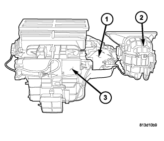
17. Install the air inlet housing (2) onto the HVAC housing (1) (refer to 24 - HEATING & AIR CONDITIONING/DISTRIBUTION - FRONT/HOUSING-HVAC - AIR INLET HOUSING - INSTALLATION).
18. Install the air distribution housing (3) onto the HVAC housing (refer to 24 - HEATING & AIR CONDITIONING/DISTRIBUTION - FRONT/HOUSING-HVAC - AIR DISTRIBUTION HOUSING - INSTALLATION).
19. Install the HVAC housing assembly (refer to 24 - HEATING & AIR CONDITIONING/DISTRIBUTION - FRONT/HOUSING-HVAC - HVAC HOUSING ASSEMBLY - INSTALLATION).
20. If the A/C evaporator is being replaced, add 60 milliliters (2 fluid ounces) of refrigerant oil to the refrigerant system. When replacing multiple A/C system components, refer to the Refrigerant Oil Capacities chart to determine how much oil should be added to the refrigerant system (refer to 24 - HEATING & AIR CONDITIONING/PLUMBING - FRONT/REFRIGERANT OIL - STANDARD PROCEDURE - REFRIGERANT OIL LEVEL). Use only refrigerant oil of the type recommended for the A/C compressor in the vehicle.