CROSSMEMBER-FRONT SUSPENSION
REMOVAL
1. Raise and support the vehicle, (Refer to LUBRICATION & MAINTENANCE/HOISTING - STANDARD PROCEDURE).
2. Remove the four wheel well screws.
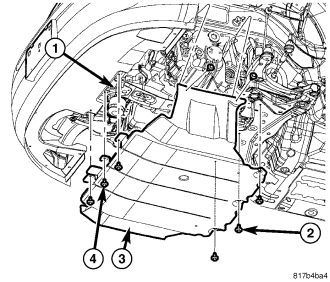
3. If equipped, remove the three front screws (4), the three rear screws (2) and one push pin fastener from the center of the belly pan.
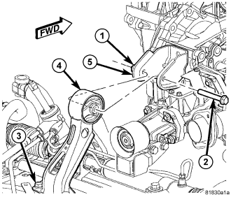
4. Remove the rear roll mount (4) through bolt (2).
5. Remove the three bolts (3) attaching the rear roll mount (5) to the crossmember and remove the mount.
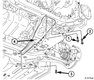
6. Remove the for/aft crossmember (4) (Refer to 13 - FRAME & BUMPERS/FRAME/CROSSMEMBER-FRONT FORE/AFT - REMOVAL).
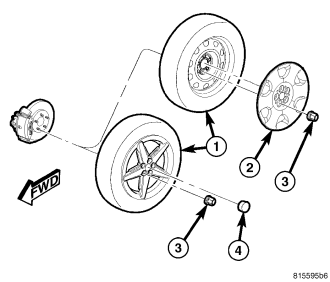
7. Remove the front wheels (1), (Refer to 22 - TIRES/WHEELS - SERVICE INFORMATION - REMOVAL).
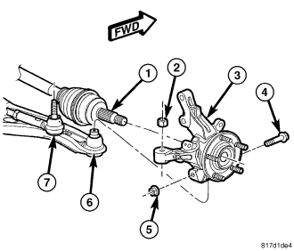
8. Remove the lower ball joint (6) pinch bolts (4) and nuts (5).
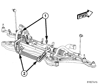
9. Remove the bolt attaching the pressure line routing bracket to the steering gear.
10. Remove the bolt attaching the return line to the crossmember.
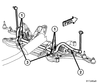
11. Remove the sway bar bushing bolts (1) and support the sway bar (2) up in the vehicle.
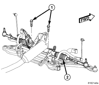
12. Remove the steering gear mounting bolts (1) and support the steering gear (2) up in the vehicle.
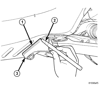
13. Mark the crossmember (3) to body location (1) using a grease pencil (2) or equivalent.
14. Support the crossmember with a suitable lifting device.
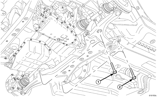
15. Remove the crossmember bolts (1 and 2) and lower the crossmember from the vehicle.
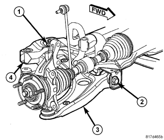
16. Remove the lower control arm (3) front pivot bolts (2).
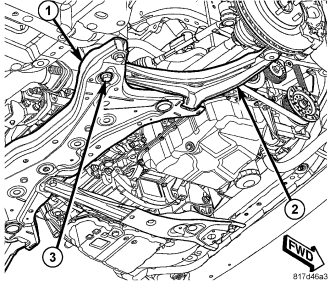
17. Remove the lower control arm rear pivot bolts (3) and separate the lower control arms from the crossmember (1).
INSTALLATION
1. Install the lower control arms and install the rear pivot bolts (3).
2. Install the front pivot bolts (2).
3. Support the crossmember on a suitable lifting device.
4. Raise the crossmember into position onto the vehicle.
5. Install the bolts (1 and 2) and align the engine cradle to the marks made during removal.
6. Tighten the bolts to 190 N·m (140 ft. lbs.).
7. Position the steering gear back into place and install the bolts (1).
8. Tighten the bolts to 61 N·m (45 ft. lbs.).
9. Position the stabilizer bar (2) back into place and install the bushing bolts (1).
10. Tighten the bolts to 61 N·m (45 ft. lbs.).
11. Position the power steering lines back into place and install the support bracket (2) bolts (1).
12. Tighten the bolts to 8 N·m (70 ft. lbs.).
13. Connect the lower ball joint stud (6) to the knuckle (3).
14. Install a NEW ball joint stud pinch bolt (4) and nut (5). Tighten the nut to 82 N·m (60 ft. lbs.).
15. Install the fore/aft crossmember (4), (Refer to 13 - FRAME & BUMPERS/FRAME/CROSSMEMBER-FRONT FORE/AFT - INSTALLATION)
16. Install the front wheels (1), (Refer to 22 - TIRES/WHEELS - INSTALLATION)
17. With the full weight of the vehicle on the suspension tighten the front control arm bushing bolts to 123 N·m (91 ft. lbs.)
18. Perform wheel alignment as necessary. (Refer to 2 - SUSPENSION/WHEEL ALIGNMENT - STANDARD PROCEDURE)
19. Install the rear roll mount (4) and install the three bolts (3) attaching it to the crossmember.
20. Tighten the bolts (3) to 153 N·m (112 ft. lbs.).
21. Install the through bolt (2) and tighten to 65 N·m (48 ft. lbs.).
22. If equipped, install the belly pan.
23. Install the three front screws (4), the three rear screws (2) and push pin fasteners into the center of the belly pan.