BG6 MANUAL TRANSAXLE
DESCRIPTION
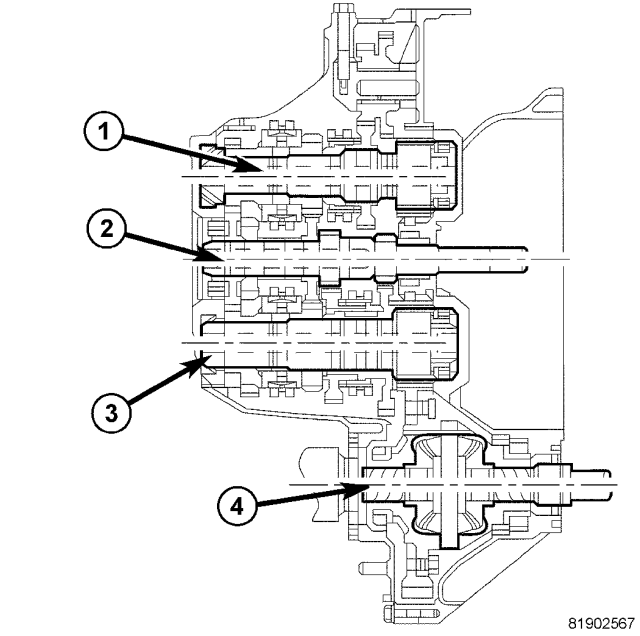
The Aisin BG 6 6-speed transaxle is a constant-mesh transaxle that is synchronized in all gear ranges.
The BG 6 transaxle is a three-shaft design, as opposed to the more common two shaft configuration, to reduce overall length of the unit for easier packaging in the vehicle. The extra shaft is an output shaft. Ratios 1-4 are on one output shaft (1); ratios 5, 6 and Reverse are on the second shaft (3). Each output shaft has a different final drive ratio, which is also different from most transaxles. All ratios are synchronized.
Synchronizers are mounted on the output shafts (1, 3) to reduce the size of the transaxle. Triple-cone synchronizers on 1st through 3rd and dual-cone synchronizers 4th and 5th gears ensure that the rotating masses of gears, shafts and the clutch disc can accelerate quickly for fast, smooth shifting.
The four-plane shift mechanism is cable operated and incorporates a pull-up ring on the shift lever that must be lifted to engage Reverse. This prevents unintentional selection of Reverse when attempting to select 1st gear. Rubber isolation of the shift system at the transaxle minimizes noise carried along the cables to the car’s interior.
| GEAR |
RATIO |
| 1ST |
3.538 |
| 2ND |
2.045 |
| 3RD |
1.367 |
| 4TH |
0.974 |
| 5TH |
0.897 |
| 6TH |
0.791 |
| REVERSE |
3.831 |
| Final Drive Ratio (FDR) |
4.059 or 3.450* |
| Overall Top Gear |
2.728 |
| *Gears 1-4 use the 4.059 final drive; gears 5th, 6th and Reverse use the 3.450 ratio. |
|
REMOVAL
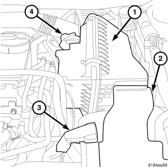
1. Remove air inlet tube (4) and air cleaner assembly (1, 2) .
2. Disconnect battery negative cable.
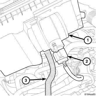
3. Unplug air flow sensor (2) at the air cleaner assembly (1).
4. Remove the Battery (Refer to 8 - ELECTRICAL/BATTERY SYSTEM/BATTERY - REMOVAL)
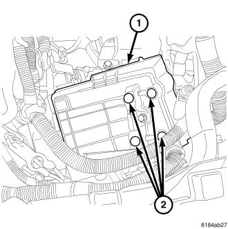
5. Remove the bolts (2) at the battery tray.
6. Remove the battery tray (1).
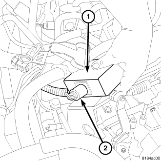
7. Unplug electrical connector (2) at the vacuum control module (1).
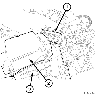
8. Unplug vacuum line connector.
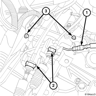
NOTE: Do not remove the shifter cable brackets from the transmission or loosen the bolts.
9. Remove clip (1) to the hydraulic clutch slave cylinder.
10. Release clips (2) at the shift cables and lift cables out of bracket slot.
11. Remove the bolts (3) at the clutch hydraulic line and move the line out of the way.
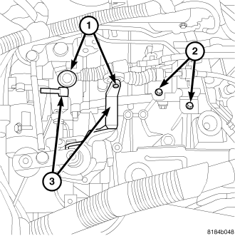
NOTE: Never loosen the shift cable bracket bolts (2).
12. Remove shift cables from shift levers (3) by tilting cable and prying from beneath with screwdriver tip.
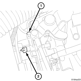
13. Remove hydraulic line (1) and the bleed adaptor (2) at the slave cylinder.
14. Unplug connectors and move wiring harness at the top of the transmission out of the way.
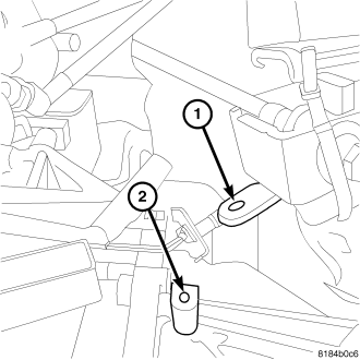
15. Support transmission with a jack.
16. Remove the bolt at the upper transmission mount (1) and lower transmission (2).
17. Remove the three upper bell housing bolts.
18. Remove the Jack from the transmission.
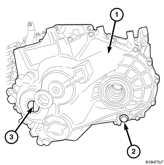
19. Raise the vehicle on the hoist.
20. Remove the drain plug (2) and drain the transmission fluid.
21. Remove both front wheels.
22. Remove the right and left halfshafts (Refer to 3 - DIFFERENTIAL & DRIVELINE/HALF SHAFT - REMOVAL) .
23. Remove left front lower splash shield.
24. Remove propeller shaft (Refer to 3 - DIFFERENTIAL & DRIVELINE/PROPELLER SHAFT - REMOVAL) .
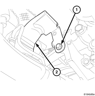
25. Remove the bolt at the catalytic converter support bracket.
26. Remove catalytic converter mounting (banjo) clamp.
27. Move the catalytic converter out of the way (Refer to 9 - ENGINE/AIR INTAKE SYSTEM/AIR CLEANER HOUSING - REMOVAL).
NOTE: One thin metallic gasket is between the catalytic converter and the exhaust pipe.
28. Remove the four PTU support brace mounting bolts.
29. Remove the PTU support bracket.
30. Remove the six PTU mounting bolts (Refer to 21 - TRANSMISSION/TRANSAXLE/POWER TRANSFER UNIT - REMOVAL).
31. Support engine and transmission with a jack.
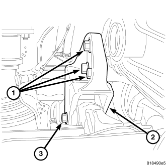
32. Remove rear transmission mount thorough bolt.
33. Remove the PTU (Refer to 21 - TRANSMISSION/TRANSAXLE/POWER TRANSFER UNIT - REMOVAL).
34. Remove the O-ring that is between the PTU and the transmission.
35. Remove the right front splash shield.
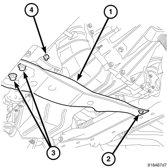
36. Remove the front transmission mount through bolt.
37. Remove the transmission crossmember bolts.
38. Remove the starter (Refer to 8 - ELECTRICAL/STARTING/STARTER MOTOR - REMOVAL)
39. Support the transmission with a transmission jack.
40. Remove the rear transmission mount retaining bolts.
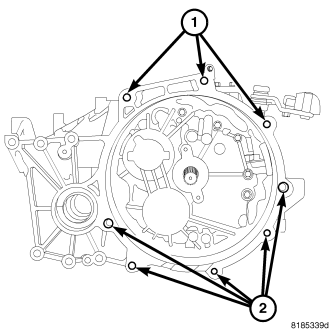
41. Remove the lower transmission bellhousing bolts.
42. Lower the transmission.
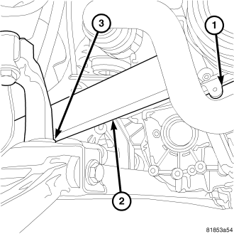
NOTE: A block of wood may be used between the frame and the engine to help gain clearance.
43. Roll engine and transmission forward to gain clearance.
44. Remove the transmission.
SPECIFICATIONS
DESCRIPTION |
SPECIFICATION |
| Transaxle Type |
Constant-mesh, fully synchronized six speed with integral differential |
| Lubrication Method |
Splash oil collected in oil troughs and distributed to mainshafts via gravity |
| GEAR |
RATIO |
| 1ST |
3.538 |
| 2ND |
2.045 |
| 3RD |
1.367 |
| 4TH |
0.974 |
| 5TH |
0.897 |
| 6TH |
0.791 |
| REVERSE |
3.831 |
| Final Drive Ratio (FDR) |
4.059 or 3.450* |
| Overall Top Gear |
2.728 |
| *Gears 1-4 use the 4.059 final drive; gears 5th, 6th and Reverse use the 3.450 ratio. |
|
DESCRIPTION |
N·m |
Ft. Lbs. |
In. Lbs. |
| Bolt (4), Concentric Slave Cylinder (CSC)-to-Bellhousing Halve |
Step 1 - 2 N·m |
— |
Step 1 - 18 In. Lbs. |
| Step 2 - 5 N·m |
— |
Step 2 - 44 In. Lbs. |
|
| Step 3 - 8.4 N·m |
— |
Step 3 - 74 In. Lbs. |
|
| Bolt (9), End Cover-to-Case |
23 |
17 |
— |
| Bolt (12), Differential Ring Gear-to-Carrier |
85 |
63 |
— |
| Bolt (4), Shift Mechanism-to-Case |
20-25 |
15-18 |
177-221 |
| Bolt (18), Transaxle Case Halve-to-Bellhousing Halve |
28 |
21 |
— |
| Detent Assembly, Shift Shaft |
20-25 |
15-18 |
177-221 |
| Plug, Shift Shaft Crossover Detent |
20-25 |
15-18 |
177-221 |
| Plug, Transaxle Drain/Fill |
39-47 |
29-35 |
345-416 |
| Switch, Back-up Lamp |
24 |
18 |
212 |
| Bolts, Flywheel- to - Crankshaft |
60 + 90* |
44 + 90* |
- |
| Bolts, Clutch cover-to-Flywheel |
22 |
16 |
195 |
| Bolts, Transaxle-to-engine |
48 |
35 |
- |
SPECIAL TOOLS
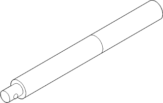
| Universal Handle C-4171 |
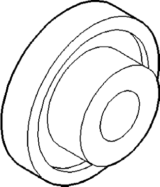
| Seal Installer 9928 |