INSTALLATION
Installation
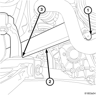
1. With engine rolled forward, lift transmission into position.
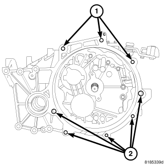
2. Install the lower transmission bolts and tighten to 48 N·m (35 ft. lbs.) torque.
NOTE: If equipped with a PTU, install the O-ring into the PTU.
3. If equipped with a PTU, install the PTU (Refer to 21 - TRANSMISSION/TRANSAXLE/POWER TRANSFER UNIT - INSTALLATION).
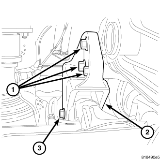
4. Roll engine and transmission back into place.
5. Install the rear transmission mount into place.
6. Install rear transmission mount bolts and tighten to 68 N·m (50 ft. lbs.).
NOTE: Do not install the rear transmission mount through bolt at this time.
7. Support the transmission with a jack.
8. Install the starter (Refer to 8 - ELECTRICAL/STARTING/STARTER MOTOR - INSTALLATION).
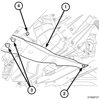
9. Install the transmission cross member and tighten to 68 N·m (50 ft. lbs.).
10. Install the front transmission mount through bolt (4) at this time and tighten to 68 N·m (50 ft. lbs.).
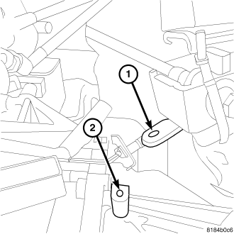
11. Install the upper transmission mount and tighten to 68 N·m (50 ft. lbs.).
12. Install the PTU support bracket and the four mounting bolts and tighten to 68 N·m (50 ft. lbs.).
13. Move the catalytic converter back into place.
NOTE: Insure that the metallic gasket is in place.
14. Install the catalytic converter banjo clamp and tighten.
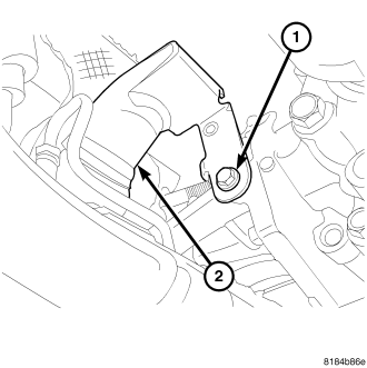
15. Install the bolt at catalytic converter support bracket and tighten to28 N·m (250 in. lbs.).
16. Install the propeller shaft into place using marks to align (Refer to 3 - DIFFERENTIAL & DRIVELINE/PROPELLER SHAFT - INSTALLATION).
NOTE: Never let propeller shaft hang with out support.
17. Install both left and right side splash shields.
18. Install left side halfshaft into transmission and the spindle.
19. Install half shafts (Refer to 3 - DIFFERENTIAL & DRIVELINE/HALF SHAFT - INSTALLATION).
20. Remove jacks.
21. Fill transmission fluid to proper level (Refer to 21 - TRANSMISSION/TRANSAXLE/MANUAL/FLUID - STANDARD PROCEDURE).
22. Fill PTU to proper fluid level, If equipped (Refer to 21 - TRANSMISSION/TRANSAXLE/POWER TRANSFER UNIT - STANDARD PROCEDURE).
23. Lower vehicle and install the upper bell housing bolts and tighten to 48 N·m (35 ft. lbs.).
24. Connect all wiring harness connectors and insure correct wiring harness is routed correctly.
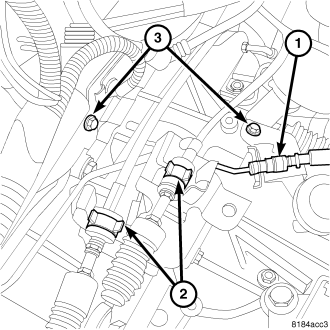
NOTE: The cable with the green clip is the inboard cable.
25. Install shift cables (2) into bracket until a click is heard.
26. Snap the ball-socket end fittings onto the shift lever ball-studs. The cable with the green clip installs at the inboard cable bracket slot.
27. Install the bolt for clutch hydraulic line and tighten to 11 N·m (105 in. lbs.).
28. Install the clutch hydraulic line to slave cylinder.
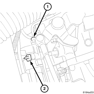
29. Install the bleed adaptor and clip at the slave cylinder.
30. Bleed the slave cylinder (Refer to 6 - CLUTCH - STANDARD PROCEDURE).
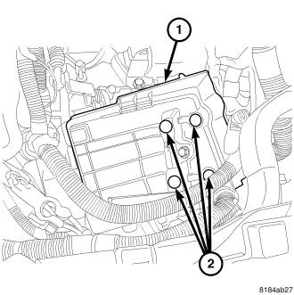
31. Install the battery tray.
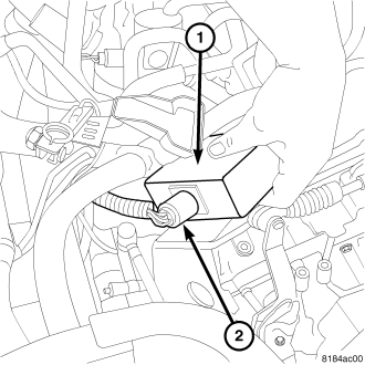
32. Plug connectors in at vacuum control module.
33. Install the battery and connect the battery cables.
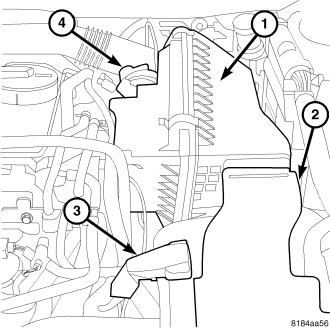
34. Install air cleaner assembly.
35. install air inlet tube.