CABLE-MODE DOOR
REMOVAL
WARNING: Disable the airbag system before attempting any steering wheel, steering column, or instrument panel component diagnosis or service. Disconnect and isolate the negative battery (ground) cable, then wait two minutes for the airbag system capacitor to discharge before performing further diagnosis or service. This is the only sure way to disable the airbag system. Failure to take the proper precautions could result in accidental airbag deployment and possible personal injury or death.
NOTE: Illustration shown with instrument panel removed for clarity.
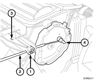
NOTE: LHD model shown. RHD model similar.
1. Disconnect and isolate the negative battery cable.
NOTE: To aid in reinstallation, note the installed position of the mode control cable to the A/C-heater control prior to removal of the cable.
2. Remove the instrument panel center bezel and disconnect the mode control cable from the A/C-heater control (refer to 23 - BODY/INSTRUMENT PANEL/BEZEL-CENTER - REMOVAL).
3. On LHD models, remove the glove box bin (refer to 23 - BODY/INSTRUMENT PANEL/BIN-GLOVE BOX - REMOVAL).
4. Disengage the metal retaining clip (1) that secures the mode control cable (2) from the right side of the HVAC air distribution housing (3).
NOTE: To aid in reinstallation, note the position of the mode control cable as it passes through the instrument panel support prior to removal of the cable.
5. Disconnect the mode control cable from the mode door cam (4) and remove the cable from the vehicle.
INSTALLATION
NOTE: Illustration shown with instrument panel removed for clarity.
NOTE: LHD model shown. RHD model similar.
1. Position the mode control cable (2) to the right side of the HVAC air distribution housing (3) through the opening in the instrument panel support.
2. Connect the mode control cable to the mode door cam (4).
3. Engage the metal retaining clip (1) to the right side of the HVAC air distribution housing. Make sure the retaining clip is fully engaged to the housing.
4. Connect the mode door control cable to the A/C-heater control and install the instrument panel center bezel (refer to 23 - BODY/INSTRUMENT PANEL/BEZEL-CENTER - INSTALLATION).
5. Visually verify the mode door cam moves from the full defrost position to the full panel position and then back to the full defrost position using the mode control knob on the A/C-heater control. If OK, go to step 10. If not OK, proceed to step 6.
CAUTION: Failure to adjust the mode control cable when required can result in operating modes not being properly obtained.
6. Disengage the mode control cable from the metal retaining clip located on the right side of the HVAC housing.
7. Turn the mode control knob on the A/C-heater control to the full defrost position.
8. Reach behind the instrument panel and turn the mode door cam clockwise until it stops in the full defrost position and engage the mode control cable to the metal retaining clip. Make sure the cam is in the full defrost position and that the cable is fully engaged to the retaining clip.
9. Verify the mode door cam moves from the full defrost position to the full panel position and then back to the full defrost position as selected with the mode control knob on the A/C-heater control. If not, repeat steps 6 thru 9.
10. On LHD models, install the glove box bin (refer to 23 - BODY/INSTRUMENT PANEL/BIN-GLOVE BOX - INSTALLATION).
11. Reconnect the negative battery cable.