OUTLETS-AIR
DESCRIPTION
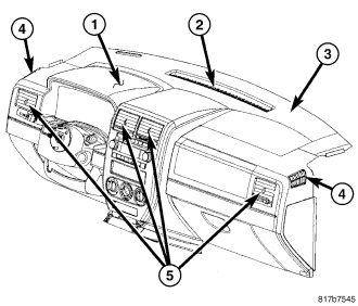
There is one defroster air outlet (2) located on the top of the instrument panel (1). The airflow from the defroster outlet is directed by fixed vanes in the outlet and cannot be adjusted. The defroster air outlet is not serviceable from the instrument panel defroster grille (3) (refer to 23 - BODY/INSTRUMENT PANEL/GRILLE-DEFROSTER - REMOVAL).
There are two side window demister air outlets (4). One located on each end of the instrument panel. The airflow from the side window demister air outlets is directed by fixed vanes in the outlets and cannot be adjusted. The side window demister air outlets are not serviceable from the instrument cluster bezel (refer to 23 - BODY/INSTRUMENT PANEL/BEZEL-CLUSTER - REMOVAL) or the instrument panel top cover (refer to 23 - BODY/INSTRUMENT PANEL/COVER-INSTRUMENT PANEL TOP - REMOVAL).
There are four rectangular instrument panel air outlets (5). One air outlet is located near each outboard end of the instrument panel facing the rear of the vehicle and two air outlets are located at the top of the instrument panel center bezel. Each of the instrument panel air outlets contain movable vanes that can direct or shut off the flow of the conditioned air leaving each of the instrument panel outlets. The driver and passenger side air instrument panel air outlets can be serviced separately. The center outlets are only serviced with the center bezel (refer to 23 - BODY/INSTRUMENT PANEL/BEZEL-CENTER - REMOVAL).
REMOVAL
NOTE: Driver side air outlet shown. Passenger side outlet similar.
1. Depending on the air outlet being serviced, remove the instrument cluster bezel (refer to 23 - BODY/INSTRUMENT PANEL/BEZEL-CLUSTER - REMOVAL) or the instrument panel top cover (refer to 23 - BODY/INSTRUMENT PANEL/INSTRUMENT PANEL TOP COVER - REMOVAL).
NOTE: If the foam seal on the air outlet is deformed or damaged, it must be replaced.
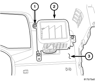
2. Remove the three screws (1) that secure the air outlet (2) to the bezel or cover (3) and remove the outlet.
INSTALLATION
NOTE: Driver side air outlet shown. Passenger side outlet similar.
1. Position the air outlet (2) onto the bezel or cover (3).
2. Install the three screws (1) that secure the air outlet. Tighten the screws to 2 N·m (17 in. lbs.).
3. Depending on the outlet being serviced, install the instrument cluster bezel (refer to 23 - BODY/INSTRUMENT PANEL/BEZEL-CLUSTER - INSTALLATION) or the instrument panel top cover (refer to 23 - BODY/INSTRUMENT PANEL/INSTRUMENT PANEL TOP COVER - INSTALLATION).