MODULE-TRANSMISSION CONTROL
- DESCRIPTION
- OPERATION
- STANDARD PROCEDURE - TRANSMISSION CONTROL MODULE INITIALIZATION
- REMOVAL
- INSTALLATION
DESCRIPTION
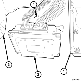
The transmission control module (TCM) is inside the car, behind the instrument panel where the clutch pedal would be located. New controllers are shipped with generic software but need to be initialized for the vehicle into which it is installed. (Refer to 8 - ELECTRICAL/ELECTRONIC CONTROL MODULES/TRANSMISSION CONTROL MODULE - STANDARD PROCEDURE)
OPERATION
Shift Control
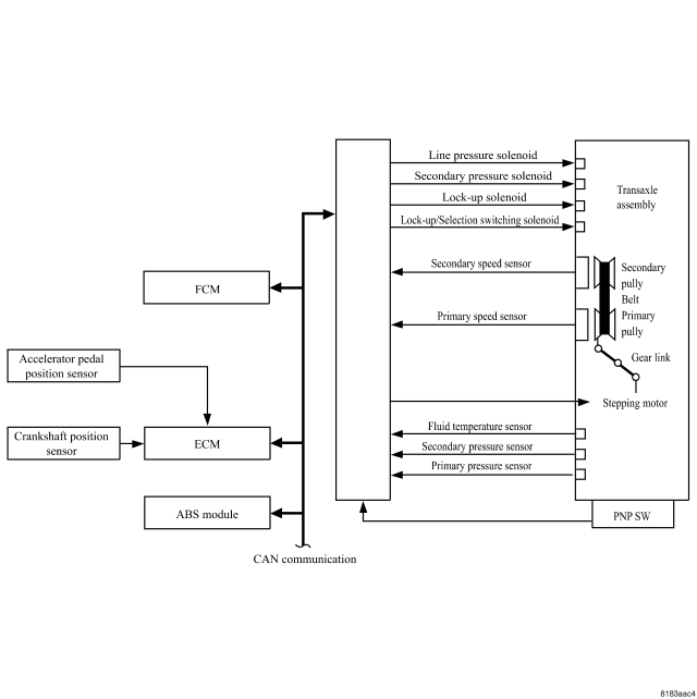
In order to select the gear ratio which can obtain the driving force in accordance with driver's intention and the vehicle condition, TCM monitors the driving conditions, such as the vehicle speed and the throttle position and selects the optimum gear ratio, and determines the gear change steps to the gear ratio. Then it sends the command to the stepping motor, and controls the flow-in/flow-out of line pressure to/from the primary pulley to determine the position of the moving-pulley and control the gear ratio.
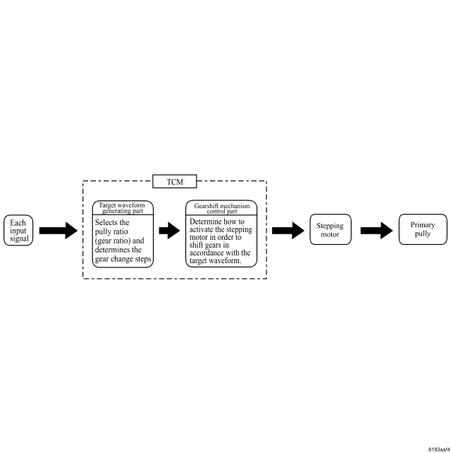
Selection of the gear ratio is set for every position separately.
“Drive” Position
Shifting is available over all the ranges of gear ratios from the lowest to the highest.
When using the Manual Mode (Vehicles with the manual mode)
When the manual mode switch is turned ON, the fixed changing gear line is set. By moving the switch to + side or – side, shift change is like a M/T and selects from a range of 6 pre-programmed gear ranges.
By limiting the shift to the area nearest the low side of the gear ratio, a larger driving force and engine brake are secured.
Downhill Engine Brake Control
When a downhill condition is detected while the accelerator pedal is released, the engine brake will be increased by downshifting so as to limit acceleration of the vehicle. Also, if uphill is detected, acceleration performance is improved by limiting the shift area on the highest side of the gear ratio.
Acceleration Control
According to vehicle speed and a increase of accelerator pedal angle, driver's request for acceleration as well as driving conditions are measured. At the time of starting or acceleration while moving, this function improves in acceleration feeling by making the engine speed proportionate to the vehicle speed. Even at the time of slower acceleration, a shift map which can gain a larger driving force is chosen for compatibility of mileage with drivability.
Line Pressure and Secondary Pressure Control
Control of line pressure and secondary pressure with a high degree of accuracy has reduced friction and improved fuel economy.
Normal Fluid Pressure Control
The line pressure and the secondary pressure are optimized depending on driving conditions, on the basis of the throttle position, the engine speed, the primary pulley (input) revolution speed, the secondary pulley (output) revolution speed, the stop lamp SW signal, the PNP switch signal, the lock-up signal, the voltage, the target gear ratio, the fluid temperature, and the fluid pressure.
Secondary Pressure Feedback Control
When controlling the normal fluid pressure or the fluid pressure at the time of selection, the secondary pressure can be set more accurately by using the fluid pressure sensor to detect the secondary pressure and performing the feedback control.
Lock-up Control
The lock-up applied gear range has been expanded by locking up the torque converter at a lower vehicle speed than conventional A/T models.
Selection Control
When selecting between N (P) and D(R) position, the optimum operating pressure is set on the basis of the throttle position, the engine speed, and the secondary pulley (output) revolution speed to lessen the select shock.
CAN Communication
Real-time communications (signal exchanges) are maintained among the control units such as the CVT, C/U, ECM, combination meter etc. Each unit is controlled optimally depending on vehicle driving conditions while sharing information and in cooperating with the other control units.
In CAN (Controller Area Network) communication, control units are connected with two communication lines (CAN-H line, CAN-L line) allowing a high rate of information to be transmitted by fewer wirings. Each control unit transmits/receives data but selectively reads required data only.
Inputs and Outputs
| Item |
Shift Control |
Line Pressure Control |
Selection Control |
Lock-up Control |
CAN Communication Control |
Fail-safe Function (Note 1) |
|
| Input |
Engine speed signal |
X |
X |
X |
X |
X |
|
| Accelerator pedal position signal |
X |
X |
X |
X |
X |
X |
|
| Closed throttle position signal |
X |
X |
X |
||||
| Stop lamp SW signal |
X |
X |
X |
X |
X |
||
| Primary pressure sensor |
X |
||||||
| Secondary pressure sensor |
X |
X |
X |
||||
| Fluid temperature sensor |
X |
X |
X |
X |
X |
||
| Primary speed sensor |
X |
X |
X |
X |
|||
| Secondary speed sensor |
X |
X |
x |
X |
X |
||
| PNP switch |
X |
X |
X |
X |
X |
||
| Output |
Line pressure solenoid value |
X |
x |
X |
|||
| Secondary pressure solenoid value |
X |
X |
X |
||||
| Lock-up solenoid value |
X |
X |
X |
||||
| Lock-up/Selection switching solenoid value |
X |
X |
X |
||||
| Stepping motor |
X |
X |
Engine/CVT Integration Control (CAN Communication Control)
In order to improve gearshift feeling and to perform controls such as prevention of engine slowdown, engine power control signals are intercommunicated between the engine ECM and the TCM, and real-time cooperative controls depending on vehicle driving conditions are performed.
TCM sends information such as fast slowdown signals, lock-up signals, torque down request signals to ECM, while receiving information such as torque down permission/prohibition signals, lock-up permission/prohibition signals, throttle position from ECM.
Fail-safe Function
If an unexpected signal is sent from any sensor, switch, solenoid etc., this function controls the CVT to make driving as smooth as possible.
Secondary Speed Sensor
The shift pattern is changed in accordance with throttle position when an unexpected signal is sent from the output speed sensor (secondary speed sensor) to the TCM. The manual mode position or the sports mode position is inhibited, and the transaxle is put in “D”.
Primary Speed Sensor
The shift pattern is changed in accordance with throttle position and secondary speed (vehicle speed) when an unexpected signal is sent from the primary speed sensor to the TCM. The manual mode function or the sports mode function is inhibited, and the transaxle is put in “D”.
PNP Switch
If an unexpected signal is sent from the PNP switch to the TCM, the transaxle is put in “D”.
Fluid Temperature Sensor
If an unexpected signal is sent from the fluid temperature sensor to the TCM, the gear ratio obtained immediately before receiving the unexpected signal is maintained and the gear ratio is controlled to keep engine speed under 5,000 rpm (approximately), depending on driving conditions.
Secondary Pressure Sensor
If an unexpected signal is sent from the secondary pressure sensor to the TCM, the secondary pressure feedback control is stopped and the offset value obtained immediately before the non-standard condition occurs is used to control line pressure.
Line Pressure Solenoid
If an unexpected condition of the solenoid is detected by the TCM, the line pressure solenoid is turned OFF to achieve the maximum fluid pressure.
Secondary Pressure Solenoid
If an unexpected condition of the secondary solenoid is detected by the TCM, the secondary pressure solenoid is turned OFF to achieve the maximum fluid pressure.
Lock-up solenoid
If an unexpected condition of the lock-up solenoid is detected by the TCM, the lock-up solenoid is turned OFF to cancel the lock-up.
Stepping Motor
If an unexpected condition of the stepping motor is detected by the TCM, the stepping motor coil phases “A” through “D” are all turned OFF to hold the gear ratio used immediately before the unexpected condition occurred.
Lock-up/Selection Switching Solenoid
If an unexpected condition of the solenoid is detected by the TCM, the lock-up/selection switching solenoid is turned OFF to cancel the lock-up.
Backup Power Supply
Transaxle assembly is protected by limiting the engine torque when the memory back-up power supply for controlling from the battery is not supplied to the TCM. Normal status is restored when turning the ignition switch OFF to ON after power is normally supplied
TCM
- 1. Shift control
- 2. Line pressure control
- 3. Selection control
- 4. Lock-up control
- 5. Engine/CVT integration control [CAN communication control]
- 6. Self-diagnosis function
- 7. Fail-safe function
Primary Speed Sensor, Secondary Speed Sensor
Primary Speed Sensor It is installed near the CVT fluid cooler in the transaxle case. It sends rotating speed of the primary pulley (input shaft) to the TCM as a pulse signal.
Secondary Speed Sensor It is installed near the output gear part in the transaxle case. It sends rotating speed of the secondary pulley (output shaft) to the TCM as a pulse signal. TCM converts the pulse signal to vehicle speed.
STANDARD PROCEDURE - TRANSMISSION CONTROL MODULE INITIALIZATION
NOTE: Refer to the following table when the Transmission Control Module (TCM) and/or transaxle has been replaced to determine if the TCM memory must be erased.
| TCM | Transaxle | Erase Memory? |
| New Module | Not Replaced | Not Required |
| Not Replaced | Replaced | Required, Refer to RELEARN, AFTER REPLACING A TRANSAXLE |
| Replaced With Used Module | N/A |
INITIAL LEARN (BRAND-NEW MODULE, MEMORY ALREADY CLEAR)
Battery must be connected. If the Totally Integrated Power Module (TIPM) is to be configured, configure the TIPM and then turn ignition key to OFF/LOCKED briefly, then back to RUN. The shifter must be in PARK or NEUTRAL, engine not running.
1. Turn the ignition key to RUN for 4 seconds to allow reading of new values.
2. Turn ignition key to OFF/LOCKED for 2 seconds to allow storing new values in EEROM.
3. Turn the ignition key to RUN, with scan tool clear DTCs.
4. Turn ignition key to OFF/LOCKED for 2 seconds.
5. After at least 7 seconds, read DTCs.
6. If DTCs resets (Refer to 21 - TRANSMISSION/TRANSAXLE/AUTOMATIC - CVT - DIAGNOSIS AND TESTING)
RELEARN, AFTER REPLACING A TRANSAXLE
1. Turn ignition key to RUN.
2. Clear learning memory using the scan tool.
3. Turn the ignition key to OFF/LOCKED for 2 seconds.
4. Turn the ignition key to RUN Clear DTCs.
5. Turn the ignition key to OFF/LOCKED for 2 seconds.
6. Turn ignition key to RUN.
7. After at least 7 seconds, read DTCs.
8. If DTCs resets (Refer to 21 - TRANSMISSION/TRANSAXLE/AUTOMATIC - CVT - DIAGNOSIS AND TESTING)
REMOVAL
1. The TCM (2) is located between the brake pedal bracket (1) and the left kick panel (3).
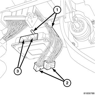
2. Unplug the two electrical connectors (2) at the TCM.
3. Remove the two nuts (1) that hold the TCM to the bulkhead.
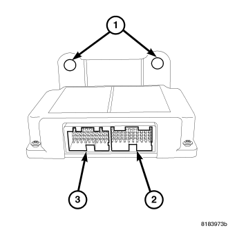
4. Remove the TCM.
INSTALLATION
1. Install TCM mounting bracket holes (1) over the two studs on the bulkhead.
2. Install the two nuts to mounting studs (1) on the bulkhead and tighten to 15 N·m (130 in. lbs.).
3. Plug in electrical connectors (2) to TCM (3).
NOTE: If a new TCM is installed a learn procedure must be performed.