PISTON & ROD-CONNECTING
DESCRIPTION
The pistons are made of a cast aluminum alloy. The pistons have pressed-in pins attached to forged connecting rods. The pistons pin is offset 0.8 mm (0.0314 in.) towards the thrust side of the piston. The connecting rods are a cracked cap design and are not repairable. The piston with rings, connecting rod and piston pin are serviced as an assembly.
REMOVAL
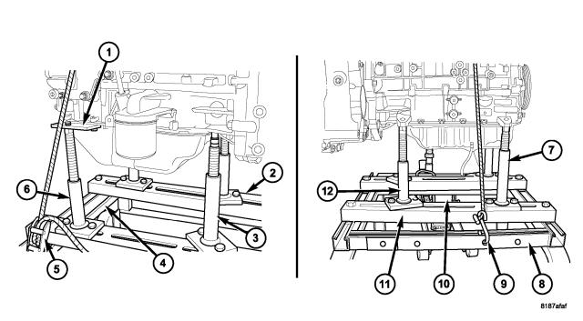
NOTE: Pistons, rings, and rods are serviced as an assembly.
CAUTION: To maintain engine balance, 1, 3, or 4 pistons can be replaced. If 2 pistons are replaced, engine will be out of balance.
1. Remove engine (Refer to 9 - ENGINE - REMOVAL).
2. Separate engine from transaxle.
3. Remove engine from dolly 6135 (8) and place on a suitable engine stand.
4. Remove cylinder head (Refer to 9 - ENGINE/CYLINDER HEAD - REMOVAL).
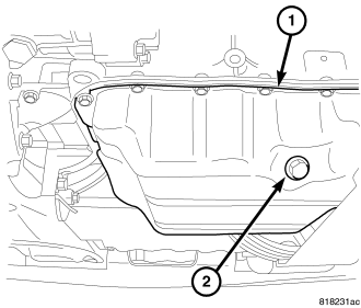
5. Drain engine oil (2).
6. Remove oil pan (1) (Refer to 9 - ENGINE/LUBRICATION/OIL PAN - REMOVAL).
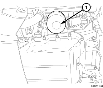
7. Remove oil filter (1).
8. Remove balance shaft assembly.
9. Remove ladder frame.
NOTE: Remove any carbon build up and clean debris from cylinder prior to piston removal to avoid scratching piston skirts.
10. Remove top ridge of cylinder bores with a reliable ridge reamer before removing pistons from cylinder block. Be sure to keep tops of pistons covered during this operation.
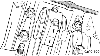
11. Rotate crankshaft so that each connecting rod is centered in cylinder bore.
12. Using a permanent ink or paint marker, identify cylinder number on each connecting rod cap .
CAUTION: DO NOT use a number stamp or a punch to mark connecting rods, as damage to connecting rod could occur.
CAUTION: Care must be taken not to damage the fractured rod and cap joint surfaces, as engine damage many occur.
13. Remove connecting rod bolts and cap.
NOTE: Do not reuse connecting rod bolts.
14. Carefully push each piston and rod assembly out of cylinder bore. Re-install bearing cap on the mating rod.
15. Repeat procedure for each piston and connecting rod assembly.
INSTALLATION
1. Install piston rings on piston (Refer to 9 - ENGINE/ENGINE BLOCK/PISTON RINGS - INSTALLATION).
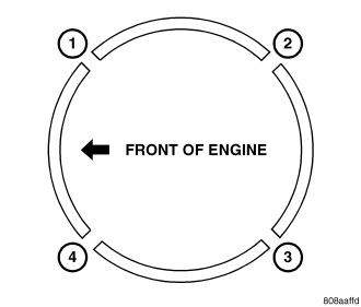
2. Before installing pistons and connecting rod assemblies into the bore, be sure that top compression ring gap (1) and the second compression ring gap (3) are staggered so that neither is in line with oil ring rail gap.
3. Before installing the ring compressor, make sure the oil ring expander ends are butted (1) and the rail gaps (2,4) located as shown above. As viewed from the top of the piston.
4. Immerse the piston head and rings in clean engine oil, slide the ring compressor, over the piston. Be sure position of rings does not change during this operation.
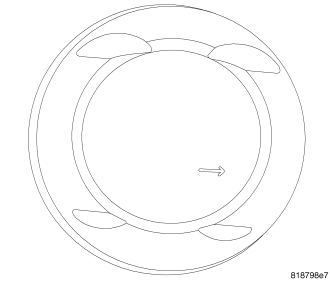
5. The directional arrow stamped on the piston should face toward the front of the engine.
6. Rotate crankshaft so that the connecting rod journal is on the center of the cylinder bore. Lubricate connecting rod journal with clean engine oil.
NOTE: There are three different size rod bearings, perform rod bearing selection procedure.
NOTE: The rod bearing sizes are indicated on the nose of the crankshaft.
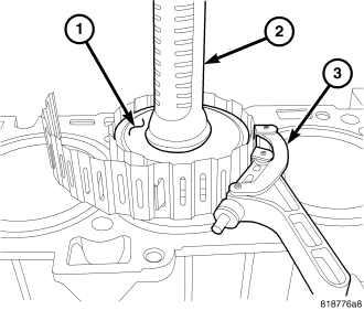
7. Install connecting rod upper bearing half into connecting rod.
8. Install ring compressor (3).
9. Tap the piston (1) down in cylinder bore, using a hammer handle (2). At the same time, guide connecting rod into position on connecting rod journal.
NOTE: The connecting rod cap bolts should NOT be reused.
10. Before installing the NEW bolts, the threads should be coated with clean engine oil.
11. Install connecting rod lower bearing half into connecting rod cap. Install connecting rod cap.
12. Install each bolt finger tight then alternately torque each bolt to assemble the cap properly.
13. Tighten the connecting rod bolts using the 2 step torque-turn method. Tighten according to the following values:
CAUTION: Do not use a torque wrench for the second step.
- Tighten the bolts to 20 N·m (15 ft. lbs.).
- Tighten the connecting rod bolts an additional 90°.
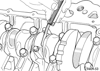
14. Using a feeler gauge, check connecting rod side clearance. (Refer to 9 - ENGINE - SPECIFICATIONS) for connecting rod side clearance.
15. Install the ladder frame (Refer to 9 - ENGINE/ENGINE BLOCK/LADDER FRAME - INSTALLATION).
16. Install oil pump/Balance Shaft Carrier Assembly (Refer to 9 - ENGINE/VALVE TIMING/BALANCE SHAFT CARRIER - INSTALLATION).
17. Install oil pan (Refer to 9 - ENGINE/LUBRICATION/OIL PAN - INSTALLATION).
18. Install cylinder head (Refer to 9 - ENGINE/CYLINDER HEAD - INSTALLATION).
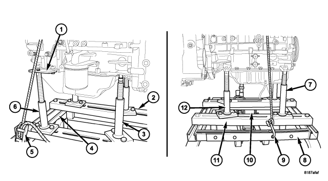
19. Install engine on dolly.
20. Connect transaxle assembly to engine.
21. Install engine (Refer to 9 - ENGINE - INSTALLATION).