CYLINDER HEAD
DESCRIPTION
The cross flow designed, aluminum cylinder head contains dual over-head camshafts with four valves per cylinder. The valves are arranged in two in-line banks. The intake valves face toward the front of the vehicle. The exhaust valves face the dash panel. The cylinder head incorporates powdered metal valve guides and seats. The cylinder head is sealed to the block using a multi-layer steel head gasket and retaining bolts.
Integral oil galleries provide lubrication passages to the variable camshaft timing phasers, camshafts, and valve mechanisms.
NOTE: Replacement cylinder heads will come complete with valves, seals, springs, retainers, keepers, lash buckets, and camshafts.
REMOVAL - CYLINDER HEAD
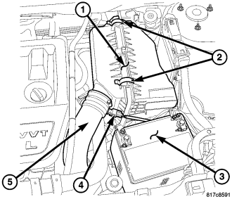
1. Perform fuel system pressure release procedure before attempting any repairs (Refer to 14 - FUEL SYSTEM/FUEL DELIVERY - STANDARD PROCEDURE).
2. Remove clean air hose and air cleaner housing (1) (Refer to 9 - ENGINE/AIR INTAKE SYSTEM/AIR CLEANER HOUSING - REMOVAL).
3. Disconnect negative cable from battery (3) .
4. Drain cooling system (Refer to 7 - COOLING - STANDARD PROCEDURE).
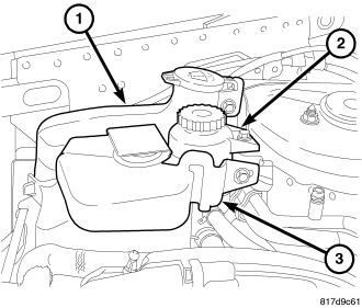
5. Remove engine cover.
6. Remove coolant recovery bottle (3) .
7. Remove and reposition power steering reservoir (2).
8. Remove power steering pump and reposition.
9. Remove windshield washer bottle (1).
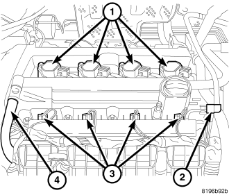
10. Disconnect breather hose.
11. Disconnect PCV hose (4).
12. Disconnect ignition coil electrical connectors (1).
13. Remove cylinder head cover.
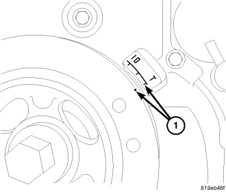
14. Raise vehicle.
15. Remove right splash shield.
16. Set engine to TDC (1).
17. Remove accessory drive belts (Refer to 7 - COOLING/ACCESSORY DRIVE/DRIVE BELTS - REMOVAL).
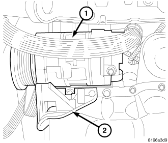
18. Remove lower A/C compressor bolts if equipped.
19. Remove lower A/C compressor mount (2) if equipped.
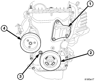
20. Remove accessory drive belt lower idler pulley.
21. Remove crankshaft damper (2).
22. Remove water pump pulley (4).
23. Remove right side engine mount bracket (1) lower bolt.
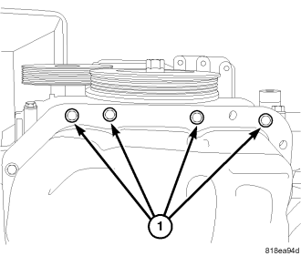
24. Remove timing chain cover lower bolts (1).
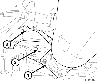
25. Disconnect oxygen sensor electrical connector (3).
26. Remove exhaust pipe at manifold (1).
27. Lower vehicle.
28. Support engine with suitable jack.
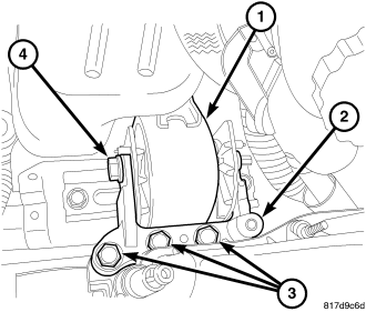
29. Remove right engine mount through bolt (4).
30. Remove right engine mount to mount bracket bolts (3).
31. Remove right engine mount adapter (2).
32. Remove accessory drive upper idler pulley.
33. Remove right upper engine mount bracket (1).
34. Remove accessory drive belt tensioner.
35. Remove upper timing chain cover retaining bolts.
36. Remove timing chain cover.
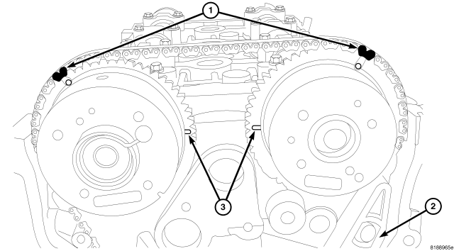
NOTE: If the timing chain plated links can no longer be seen, the timing chain links corresponding to the timing marks must be marked prior to removal if the chain is to be reused.
37. Mark chain link (1) corresponding to camshaft timing mark.
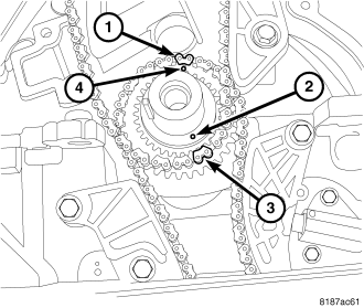
38. Mark chain link (3) corresponding to crankshaft timing mark (2).
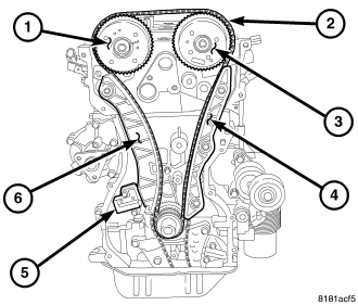
39. Remove timing chain tensioner (5).
40. Remove timing chain (2).
41. Remove timing chain guides (4,6).
42. Disconnect fuel line at the fuel rail (2).
43. Disconnect fuel injector electrical connectors (3).
44. Disconnect top engine electrical connectors and reposition harness.
45. Remove fuel rail.
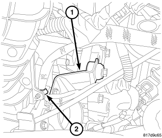
46. Remove throttle body support bracket retaining bolt (2).
47. Disconnect electronic throttle control electrical connector.
48. Disconnect map sensor electrical connector.
49. Disconnect vacuum lines at intake.
50. Remove intake manifold retaining bolts.
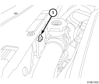
51. Remove upper radiator hose retaining bolt (1).
52. Remove intake manifold.
53. Remove coolant outlet manifold and set aside.
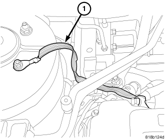
54. Remove ground strap (1) at right rear of cylinder head.
55. Remove exhaust manifold (Refer to 9 - ENGINE/MANIFOLDS/EXHAUST MANIFOLD - REMOVAL).
56. Remove camshafts (Refer to 9 - ENGINE/CYLINDER HEAD/CAMSHAFT(S) - REMOVAL).
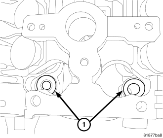
NOTE: All of the cylinder head bolts have captured washersEXCEPTthe front two (1).
57. Remove cylinder head bolts.
58. Remove cylinder head from engine block.
59. Remove front cylinder head bolt washers (1).
60. Inspect and clean cylinder head and block sealing surfaces. Refer to Cleaning and Inspection in this section for procedures.
NOTE: Ensure cylinder head bolt holes in the block are clean, dry (free of residual oil or coolant), and threads are not damaged.
CLEANING
To ensure engine gasket sealing, proper surface preparation must be performed, especially with the use of aluminum engine components and multi-layer steel cylinder head gaskets.
NOTE: Multi-Layer Steel (MLS) head gaskets require a scratch free sealing surface.
Remove all gasket material from cylinder head and block (Refer to 9 - ENGINE - STANDARD PROCEDURE). Be careful not to gouge or scratch the aluminum head sealing surface.
Clean all engine oil passages.
INSPECTION
NOTE: Replacement cylinder heads will come complete with valves, seals, springs, retainers, keepers, lash buckets, and camshafts.
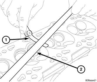
1. Cylinder head must be flat within 0.1 mm (0.004 in.) .
2. Inspect camshaft bearing journals for scoring.
3. Remove carbon and varnish deposits from inside of valve guides with a reliable guide cleaner.
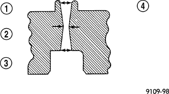
4. Using a small hole gauge and a micrometer, measure valve guides in 3 places top (1), middle (2), and bottom (3). (Refer to 9 - ENGINE - SPECIFICATIONS) Replace guides if they are not within specification.
5. Check valve guide height.
6. Prior to installing cylinder head, the cylinder block should be checked for flatness (Refer to 9 - ENGINE/ENGINE BLOCK - INSPECTION).
INSTALLATION - CYLINDER HEAD
NOTE: Ensure cylinder head bolt holes in the block are clean, dry (free of residual oil or coolant), and threads are not damaged.
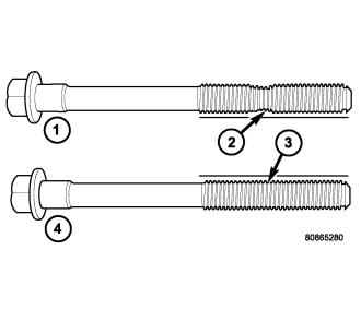
NOTE: The Cylinder head bolts should be examined BEFORE reuse. If the threads are necked down, the bolts should be replaced.
Necking can be checked by holding a scale or straight edge against the threads. If all the threads do not contact the scale (2), the bolt should be replaced.
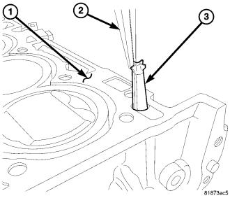
CAUTION: Always replace the variable valve timing filter screen (3) when servicing the head gasket or engine damage could result.
1. Replace the variable valve timing filter screen (3).
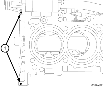
NOTE: When using RTV, the sealing surfaces must be clean and free from grease and oil.
NOTE: When using RTV, parts should be assembled in 10 minutes and tighten to final torque within 45 minutes.
2. Place two pea size dots of Mopar® engine sealant RTV or equivalent (1) on cylinder block as shown.
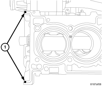
3. Position the new cylinder head gasket on engine block with the part number facing up. Ensure gasket is seated over the locating dowels in block.
4. Place two pea size dots of Mopar® engine sealant RTV or equivalent (1) on cylinder head gasket as shown.
5. Position cylinder head onto engine block.
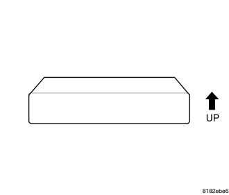
NOTE: The front two cylinder head bolts do not have captured washers. The washers must be installed with the bevel up towards the bolt head.
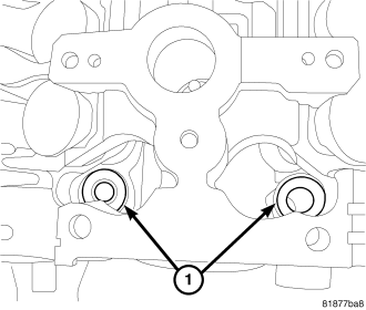
6. Install washers (1) for the front two cylinder head bolts.
7. Before installing the bolts, the threads should be lightly coated with engine oil.
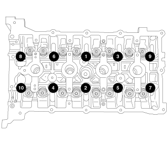
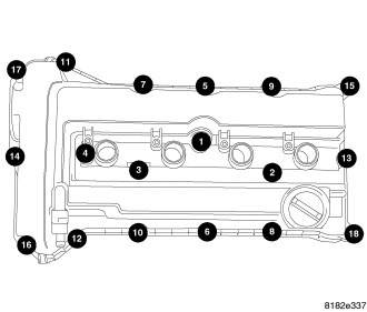
8. Install the cylinder head bolts and tighten in the sequence shown.
- First: All to 30 N·m (25 ft. lbs.)
- Second: All to 61 N·m (45 ft. lbs.)
- Third: All to 61 N·m (45 ft. lbs.)
- Fourth: All an additional 90°
CAUTION: Do not use a torque wrench for the Fourth step.
9. Clean excess RTV from timing chain cover sealing surface.
10. Install camshafts. (Refer to 9 - ENGINE/CYLINDER HEAD/CAMSHAFT(S) - INSTALLATION).
11. Install cylinder head cover (Refer to 9 - ENGINE/CYLINDER HEAD/CYLINDER HEAD COVER - INSTALLATION).
12. On AWD vehicles install maniverter (Refer to 9 - ENGINE/MANIFOLDS/EXHAUST MANIFOLD - INSTALLATION).
13. On FWD vehicles install exhaust manifold (Refer to 9 - ENGINE/MANIFOLDS/EXHAUST MANIFOLD - INSTALLATION).
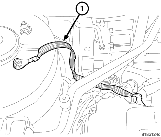
14. Install ground strap (1) at right rear of cylinder head.
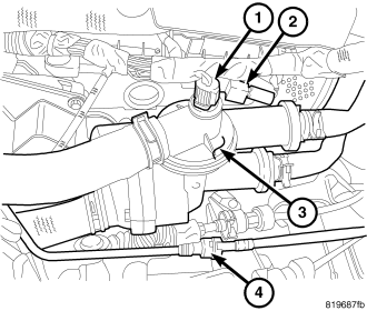
15. Install coolant adapter (3) with new seals.
16. Connect coolant hoses.
17. Connect purge hose (4).
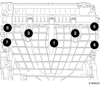
18. Install intake manifold.
19. Install intake manifold bolts and tighten to 24 N·m (18 ft. lbs.).
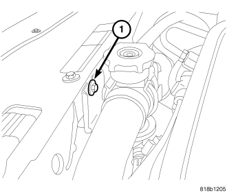
20. Install upper radiator hose retaining bracket bolt (1).
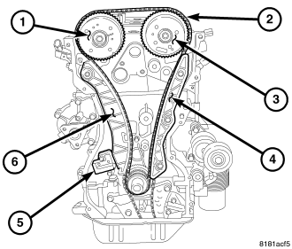
21. Install timing chain (2) (Refer to 9 - ENGINE/VALVE TIMING/TIMING BELT/CHAIN AND SPROCKETS - INSTALLATION).
22. Install timing chain cover (Refer to 9 - ENGINE/VALVE TIMING/TIMING BELT / CHAIN COVER(S) - INSTALLATION).
23. Remove coils from cylinder head cover.
24. Install cylinder head cover (Refer to 9 - ENGINE/CYLINDER HEAD/CYLINDER HEAD COVER(S) - INSTALLATION).
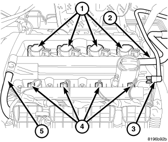
25. Connect cam sensor wiring connector.
26. Install spark plugs and tighten to 27 N·m (20 ft.lbs.).
27. Install ignition coils (1) and tighten to 8 N·m (70 in.lbs.).
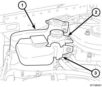
28. Install power steering pump reservoir (2).
29. Install windshield washer reservoir (1).
30. Install coolant recovery reservoir (3)
31. Install accessory drive belts (Refer to 7 - COOLING/ACCESSORY DRIVE/DRIVE BELTS - INSTALLATION).
32. Connect engine coolant temperature sensor connector.
33. Connect coolant hoses to coolant adapter (3). Connect heater hoses (1) to thermostat housing.
34. Connect coolant temperature sensor (1) and capacitor (2) electrical connectors.
35. Install heater tube support bracket to cylinder head.
36. Install fastener attaching dipstick tube to lower intake manifold.
37. Connect coil (1) and injector (4) electrical connectors.
38. Install fuel rail.
39. Connect fuel supply line quick-connect (3) at the fuel rail assembly (Refer to 14 - FUEL SYSTEM/FUEL DELIVERY/QUICK CONNECT FITTING - STANDARD PROCEDURE).
40. Fill cooling system (Refer to 7 - COOLING/ENGINE - STANDARD PROCEDURE).
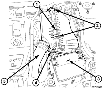
41. Connect negative cable to battery (3).
42. Install clean air hose (5) and air cleaner housing (1) (Refer to 9 - ENGINE/AIR INTAKE SYSTEM/AIR CLEANER HOUSING - INSTALLATION).
43. Install new oil filter and fill engine with oil.
44. Start engine and check for leaks.
45. Install engine cover.