ENGINE 2.4L WORLD
DESCRIPTION
The 2.4 Liter (148 cu. in.) in-line four cylinder engine is a double over head camshaft design with mechanical lash tappets and four valves per cylinder design. This engine is NOT free-wheeling; meaning that the pistons will contact the valves in the event of a timing chain failure.
The cylinders are numbered from front of the engine to the rear. The firing order is 1–3–4–2.
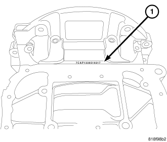
The engine serial number (1) is located on the rear of the cylinder block behind the oil pan. The serial number is visable with the oil pan in place. The serial number contains engine build date information.
REMOVAL - ENGINE ASSEMBLY
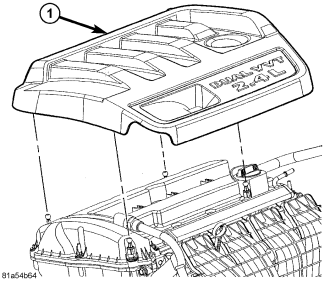
1. Remove engine cover (1).
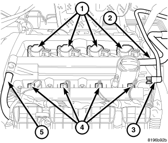
2. Perform fuel pressure release procedure (Refer to 14 - FUEL SYSTEM/FUEL DELIVERY - STANDARD PROCEDURE), then disconnect and remove fuel line (3).
3. Remove make-up air hose (2).
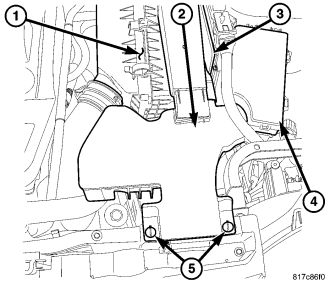
4. Loosen retainers (5) and remove air inlet tube (2).
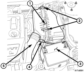
5. Disconnect intake air temperature sensor electrical connector (4).
6. Remove clean air tube from air cleaner housing (5).
7. Remove air cleaner housing assembly (1) (Refer to 9 - ENGINE/AIR INTAKE SYSTEM/AIR CLEANER HOUSING - REMOVAL).
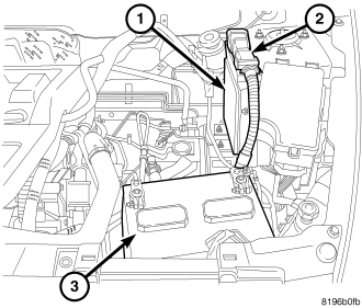
8. Disconnect both cables from battery and remove battery (3).
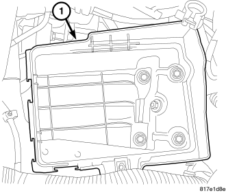
9. Remove battery tray (1).
10. Discharge air conditioning system, if equipped (Refer to 24 - HEATING & AIR CONDITIONING/PLUMBING - STANDARD PROCEDURE).
11. Drain cooling system (Refer to 7 - COOLING - STANDARD PROCEDURE).
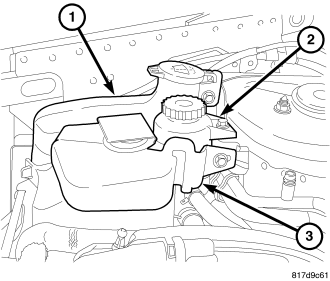
12. Remove coolant reservoir (3).
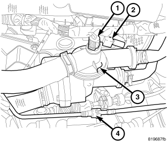
13. Remove coolant hoses from coolant adapter (3).
14. Disconnect coolant temperature sensor connector (1) and capacitor connector (2).
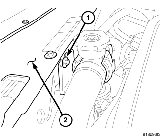
15. Remove upper radiator hose support (1).
16. Disconnect coils (1), injectors (4), cam sensors, oil temperature sensor, and oil control valve electrical connectors and reposition harness.
17. Remove PCV hose (5) from valve cover.
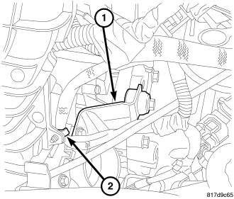
18. Remove harness from intake (2).
19. Remove throttle body support bracket (1).
20. Remove vacuum lines from throttle body and intake manifold.
21. Disconnect electronic throttle control and manifold flow control valve electrical connectors.
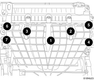
22. Remove dipstick.
23. Remove intake bolts (1-7) and remove intake.
24. Disconnect coolant temperature sensor at block, knock sensor, oil pressure sensor, generator, starter, block heater (if equipped), A/C compressor (if equipped), and block ground.
25. Remove accessory drive belt.
26. Remove power steering reservoir (2).
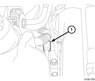
27. Remove power steering line support at engine mount (1).
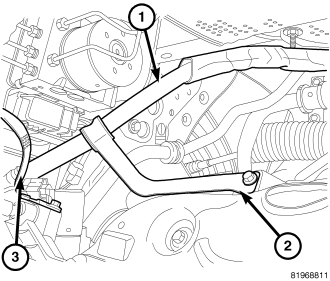
28. On FWD vehicles, remove power steering hose support from exhaust manifold (2).
29. Remove power steering pump and set aside.
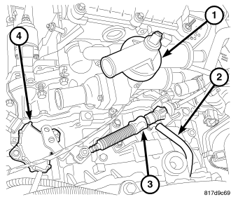
30. Vehicles equipped with an automatic transaxle
a. Remove transaxle filler tube.
b. Disconnect transmission linkage (3).
c. Remove transmission vent hose (2).

31. Vehicles equipped with a manual transaxle remove shift linkage (1) by squeezing the tabs of retainer (2) and lifting upwards on shift cable.
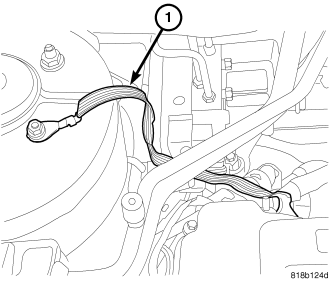
32. Remove ground strap (1) at right strut tower.
33. Raise vehicle.
34. Remove wheels.
35. Remove front splash shield.
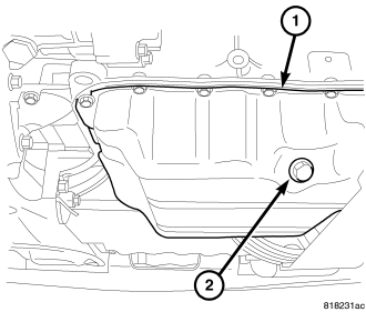
36. Remove front axle shafts (Refer to 3 - DIFFERENTIAL & DRIVELINE/HALF SHAFT - REMOVAL).
37. Drain oil (2).
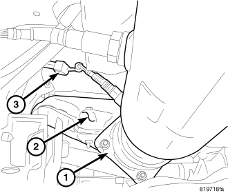
38. On AWD vehicles, remove maniveter (Refer to 9 - ENGINE/MANIFOLDS/EXHAUST MANIFOLD - REMOVAL).
39. Remove exhaust pipe to exhaust manifold bolts (1).
40. Disconnect oxygen sensor connector (3).
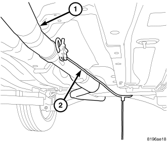
41. On FWD vehicles, pull the exhaust pipe (1) rearward with a suitable strap (2).
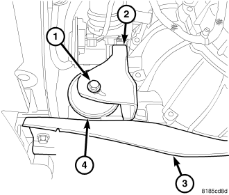
42. Remove front mount through bolt (1).
43. Remove fore/aft member (3).
44. Remove front mount bracket (2).
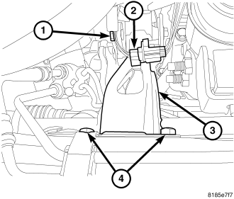
45. Remove rear mount (3) (Refer to 9 - ENGINE/ENGINE MOUNTING/REAR MOUNT - REMOVAL).
46. On AWD vehicles, remove PTU assembly (Refer to 21 - TRANSMISSION/TRANSAXLE/POWER TRANSFER UNIT - REMOVAL).
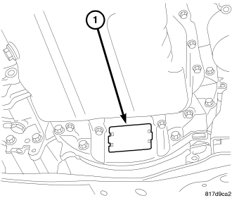
47. Remove inspection cover (1) and mark torque converter to flywheel.
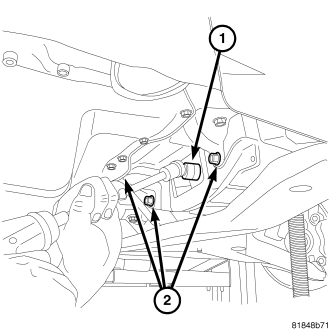
48. On vehicles equipped with an automatic transaxle, remove torque converter bolts (1).
49. On vehicles equipped with an manual transaxle, remove modular clutch bolts (1).
50. Remove lower bellhousing bolts (2).
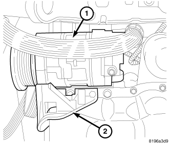
51. Remove A/C lines from compressor and remove A/C compressor (1).
52. Remove A/C compressor mounting bracket (2).
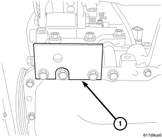
53. Install adapter plate 9704 (1).
54. Remove generator and lower idler pulley.
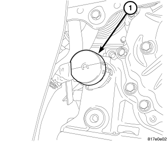
55. On vehicles equipped with an automatic transaxle, disconnect transmission electrical connector (1).
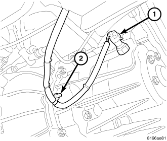
56. On vehicles equipped with an manual transaxle, disconnect transmission electrical connector (1) and harness retainer (2).
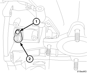
57. Disconnect CKP (2) electrical connector.
58. On vehicles equipped with an automatic transaxle, remove transaxle coolant lines from cooler.
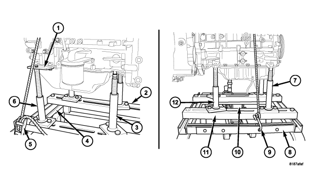
59. Position dolly (4,8) under engine and lower vehicle.
WARNING: Safety straps MUST be used.
60. Install safety straps (5,9).
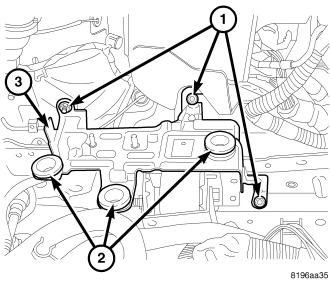
61. Remove PCM bracket retaining bolts (1) and remove pcm bracket (3).
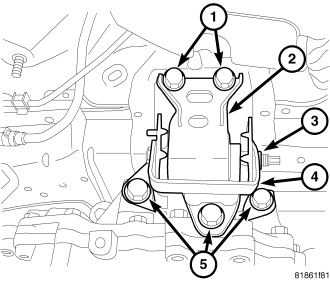
62. Remove left engine mount bracket retaining bolts (5).
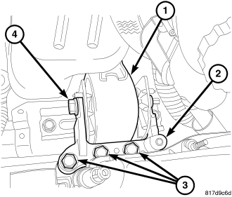
63. Remove right engine mount bracket retaining bolts (3).
64. Raise vehicle away from engine and transaxle.
65. Separate engine from transaxle.
INSTALLATION - ENGINE ASSEMBLY
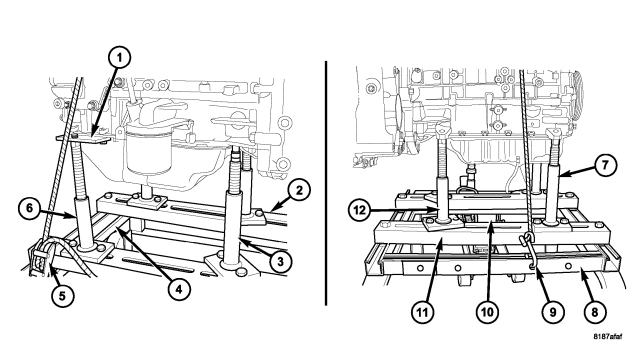
1. Position engine and transmission assembly under vehicle and slowly lower the vehicle over the engine/transaxle assembly.
2. Continue lowering vehicle until engine/transaxle aligns to mounting locations.
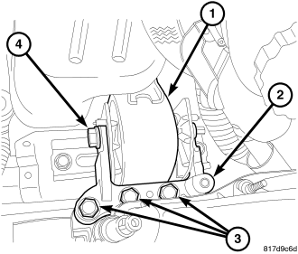
3. Install mounting bolts (3) at the right mount bolts and tighten bolts to 118 N·m (87 ft. lbs.).
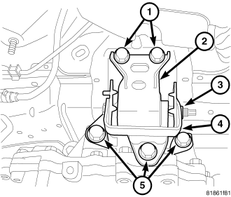
4. Install mounting bolts (5) at the left mount bolts and tighten bolts to 118 N·m (87 ft. lbs.).
5. Remove safety straps (5,9) from engine/transaxle assembly. Slowly raise vehicle enough to remove the engine dolly and cradle.
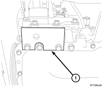
6. Remove adapter plate 9704 (1).
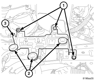
7. Install pcm bracket (3) and tighten retainers (1).
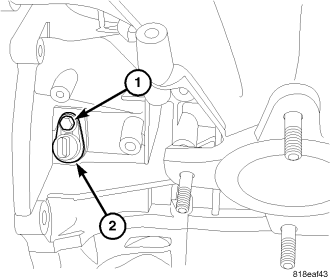
8. Connect CKP (2) electrical connector (2).
9. On AWD vehicles, install PTU (Refer to 21 - TRANSMISSION/TRANSAXLE/POWER TRANSFER UNIT - INSTALLATION).
10. On AWD vehicles, install maniverter (Refer to 9 - ENGINE/MANIFOLDS/EXHAUST MANIFOLD - INSTALLATION).
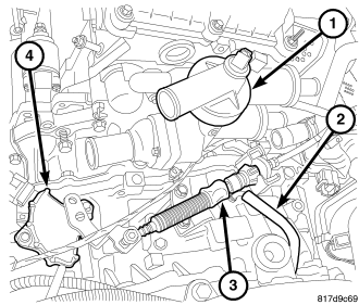
11. Vehicles equipped with an automatic transaxle
a. Install transaxle linkage (3) and adjust as necessary.
b. Install transaxle vent hose (2).
c. Install dipstick tube.
12. Vehicles equipped with a manual transaxle
a. Install shift linkage.
b. Connect clutch hydraulic line.
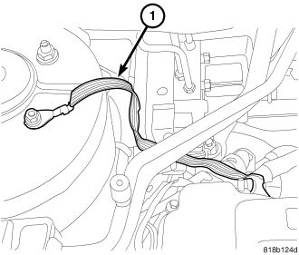
13. Install Ground strap (1).
14. Raise vehicle.
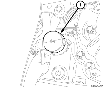
15. On vehicles equipped with an automatic transaxle, connect transaxle electrical connector.
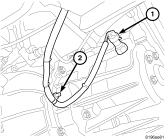
16. On vehicles equipped with a manual transaxle, connect transaxle electrical connector (1) and install harness retainer (2).
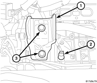
17. Install rear mount bracket (1).
18. Install rear mount and tighten bolts (3).
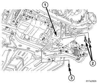
19. Install front mount bracket and tighten bolts.
20. Install fore/aft member (1).
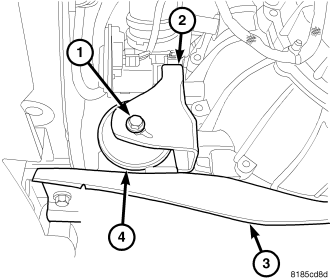
21. Install front mount through bolt and tighten.
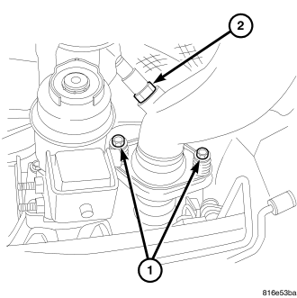
22. On AWD vehicles, install maniverter to exhaust pipe bolts (1) and tighten bolts.
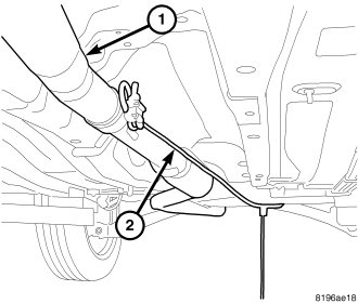
23. On FWD vehicles, remove strap (2) from exhaust pipe (1).
24. On FWD vehicles, install new exhaust manifold gasket and install catalytic converter to exhaust manifold and tighten.
25. Connect oxygen sensor connector.
26. Install generator.
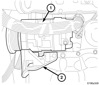
27. Install A/C bracket (2).
28. Install A/C lines on compressor and install compressor (1).
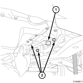
29. Install lower bell housing bolts (2) and tighten bolts.
30. Align torque converter/modular clutch assembly and flex plate mark. Install torque converter/modular clutch assembly bolts and tighten.
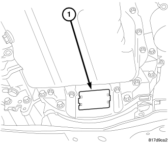
31. Install inspection cover (1).
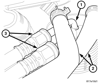
32. On vehicles equipped with an automatic transaxle, connect trans cooler lines (3).
33. On vehicles equipped with an automatic transaxle, install coolant hoses (2) at transmission cooler (1).
34. Install axles (Refer to 3 - DIFFERENTIAL & DRIVELINE/HALF SHAFT - INSTALLATION).
35. Install splash shields.
36. Install wheels.
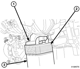
37. Install oil cooler if equipped (2) (Refer to 9 - ENGINE/LUBRICATION/OIL COOLER & LINES - INSTALLATION).
38. Connect coolant hoses to oil cooler (2), if equipped.
39. Install new oil filter (3).
40. Lower vehicle.
41. Install upper idler pulley.
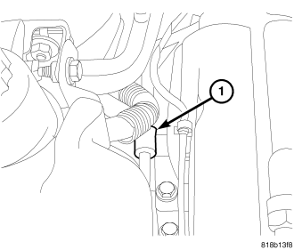
42. Install power steering pump.
43. Install power steering line support bracket at engine mount (1).
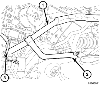
44. On FWD vehicles, install power steering hose support (2) at exhaust manifold.
45. Install accessory drive belt.
46. Connect electrical connectors at block ground, starter, A/C compressor, knock sensor, Oil pressure sensor, generator, Coolant temperature sensor at block, and block heater.
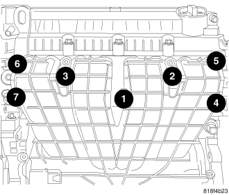
47. Install intake manifold and tighten bolts as shown.
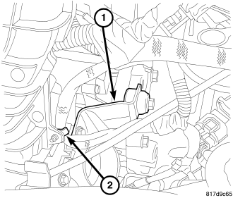
48. Install throttle body support bracket (1).
49. Install engine oil dip stick.
50. Install vacuum lines at throttle body and intake manifold.
51. Connect manifold flow control valve and electronic throttle control electrical connectors and fasten harness to intake.
52. Install intake air tube on throttle body.
53. Install PCV hose (5) to valve cover.
54. Connect fuel line (3) to fuel rail.
55. Connect coils (1), injectors (4), oil temperature sensor, cam position sensors.
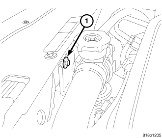
56. Install upper radiator support bracket (1).
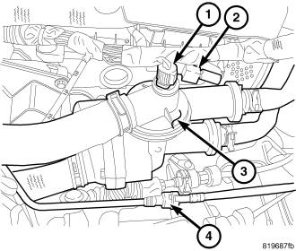
57. Connect engine coolant temperature sensor (1), and capacitor (2).
58. Install coolant hoses at coolant adapter (3).
59. Connect purge hose (4).
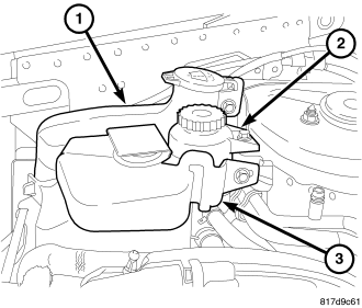
60. Install coolant reservoir (3) and connect hose.
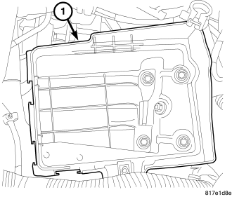
61. Install battery tray (1).
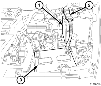
62. Install battery (3).
63. Connect battery cables.
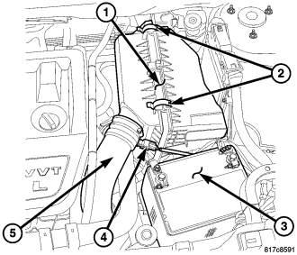
64. Install air cleaner housing (1) and connect inlet air hose (5).
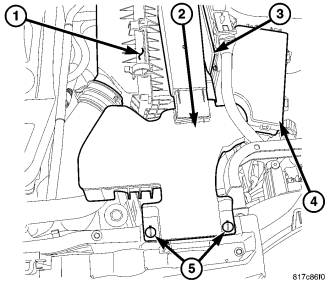
65. Install fresh air inlet (2) and tighten retainers (5).
66. Fill with coolant (Refer to 7 - COOLING - STANDARD PROCEDURE).
67. Fill with oil.
CAUTION: Do NOT run the engine with a vacuum pump in operation or with a vacuum present within the A/C system. Failure to follow this caution will result in serious A/C compressor damage.
68. Evacuate the refrigerant system (refer to 24 - HEATING & AIR CONDITIONING/PLUMBING - STANDARD PROCEDURE - REFRIGERANT SYSTEM EVACUATE).
69. Charge the refrigerant system (refer to 24 - HEATING & AIR CONDITIONING/PLUMBING - STANDARD PROCEDURE - REFRIGERANT SYSTEM CHARGE).
70. Start engine and check for leaks.
71. Install engine cover.