HUB / BEARING
DESCRIPTION
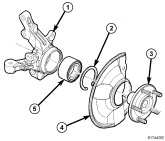
The wheel bearing (5) and hub (3) are pressed into the knuckle (1). The wheel bearing is secured in place using a snap ring.
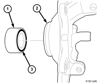
One side of the wheel bearing has an integrated magnetic encoder ring for wheel speed sensor usage as equipped. It is important that the wheel speed sensor magnetic encoder ring (dark band) (3) be positioned to the inside of the knuckle or the wheel speed sensor will not operate correctly.
The wheel bearing is a Unit 1 type cartridge bearing that requires no maintenance. The wheel bearing can be serviced separately from the hub.
The hub supports the driveline halfshaft outer constant velocity (C/V) joint. Each is splined and meshes in the center of the hub. The outer C/V joint is retained to the hub using a nut. The nut is locked to the outer C/V stub shaft using a cotter pin.
The hub has five studs pressed into its flange.
REMOVAL
NOTE: The removal and installation of the wheel bearing and hub from the knuckle is only to be done with the knuckle removed from the vehicle.
1. Remove the steering knuckle from the vehicle. (Refer to 2 - SUSPENSION/FRONT/KNUCKLE - REMOVAL)
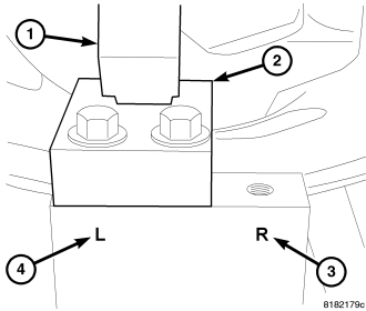
2. Position the locator block (2) for Fixture, Special Tool 9712, as follows:
a. For left side knuckles, place the locator block (2) to the left side (4) on the Fixture. The side of the locator block with the angle cut goes downward, toward the Fixture. Install the mounting screws and tighten them to approximately 54 N·m (40 ft. lbs.).
b. For right side knuckles, place the locator block (2) to the right side (3) on the Fixture. The side of the locator block with the angle cut goes downward, toward the Fixture. Install the mounting screws and tighten them to approximately 54 N·m (40 ft. lbs.).
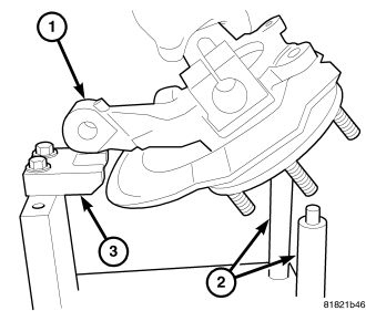
3. Install the knuckle in the Fixture as shown, guiding the steering arm (1) to rest on the locator block (3) and the brake caliper mounting bosses on the two Fixture pins (2).
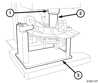
4. Place the Fixture (3) with knuckle in an arbor press.
5. Position Remover/Installer, Special Tool 9712-2 (2), in the small end of the hub. Lower the arbor press ram (1) and remove the hub from the wheel bearing and knuckle. The bearing race will normally come out of the wheel bearing with the hub as it is pressed out of the bearing.
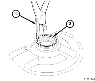
6. Remove the knuckle from the Fixture and turn it over.
7. Remove the snap ring (2) from the knuckle using an appropriate pair of snap ring pliers (1).
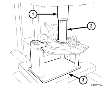
8. Place the knuckle back in the Fixture (3) in the arbor press ram.
9. Place Installer (2), Special Tool MD-998334, on the outer race of the wheel bearing. Lower the arbor press ram (1) and remove the wheel bearing from the knuckle.
10. Remove the knuckle and tools from arbor press.
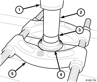
11. If the bearing race is still pressed onto the hub, install the Bearing Splitter (5), Special Tool 1130, between the hub flange and the bearing inner race (4).
12. Place the hub, bearing race and Bearing Splitter in an arbor press. The press support blocks must not obstruct the wheel hub while it is being pressed out of the bearing race.
13. Place Remover/Installer (2), Special Tool 9712-2, in the end of the hub (3). Lower the arbor press ram (1) and remove the hub from the bearing race.
NOTE: For installation, (Refer to 2 - SUSPENSION/FRONT/HUB / BEARING - INSTALLATION).
INSTALLATION
CAUTION: When installing the wheel bearing (1) in the knuckle (2) it is important to place the side of bearing with the wheel speed sensor magnetic encoder ring (dark band) (3) in the knuckle first. Otherwise, the wheel speed sensor will not operate correctly.
1. Wipe the bearing bore of the knuckle clean of any grease or dirt with a clean, dry shop towel.
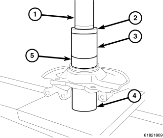
2. Place the knuckle in an arbor press supporting the knuckle from underneath using Cup (4), Special Tool 6310-1.
3. Place the NEW wheel bearing (5) magnetic encoder ring side down (see above Caution) into the bore of the knuckle. Be sure the wheel bearing is placed squarely into the bore.
4. Place Receiver (3), Special Tool 8498, larger inside diameter end down over the outer race of the wheel bearing.
5. Place Disc (2), Special Tool 6310-2, into top of Receiver 8498. Lower the arbor press ram (1) and press the wheel bearing into the knuckle until it is bottomed in the bore of the knuckle.
6. Remove the knuckle and tools from the arbor press.
7. Install a NEW snap ring (2) in the knuckle using an appropriate pair of snap ring pliers (1). Make sure the snap ring is fully seated.
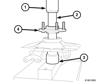
8. Place the knuckle in an arbor press. Support the knuckle from underneath using Remover/Installer (3), Special Tool MB-990799, smaller end up against the wheel bearing inner race.
9. Place the hub (4) in the wheel bearing making sure it is square with the bearing inner race.
10. Position Remover/Installer, Special Tool 9712-2 (2), in the end of the hub. Lower the arbor press ram (1) and press the hub into the wheel bearing until it bottoms.
11. Remove the knuckle and tools from the press.
12. Verify the hub turns smoothly without rubbing or binding.
13. Install the knuckle on the vehicle. (Refer to 2 - SUSPENSION/FRONT/KNUCKLE - INSTALLATION)