FUEL TANK
DESCRIPTION
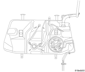
The fuel tank is constructed of a plastic material. Its main functions are for fuel storage and for placement of the fuel pump module. The tank is made from High density Polyethylene (HDPE) material. If equipped with ORVR (Onboard Refueling Vapor Recovery) it has been added to the fuel tank to control refueling vapor emissions.
OPERATION
All models pass a full 360 degree rollover test without fuel leakage. To accomplish this, fuel and vapor flow controls are required for all fuel tank connections.
All models are equipped with either one or two check valves mounted into the top of the fuel tank (or pump module).
An evaporation control system is connected to the check valve(s)/control valve to reduce emissions of fuel vapors into the atmosphere, when the tank is vented due to vapor expansion in the tank. When fuel evaporates from the fuel tank, vapors pass through vent hoses or tubes to a charcoal canister where they are temporarily held. When the engine is running, the vapors are drawn into the intake manifold. In addition, fuel vapors produced during vehicle refueling are allowed to pass through the vent hoses/tubes to the charcoal canister(s) for temporary storage (prior to being drawn into the intake manifold). All models are equipped with a self-diagnosing system using a ESIM (Evaporative System Integrity Monitor) Refer to the Emission Control System for additional information.
INLET CHECK VALVE
All vehicles have an inlet check valve on the inside of the fuel tank at the filler inlet
The valve prevents fuel from splashing back on customer during vehicle refueling. The valve is a non-serviceable item.
REMOVAL
WARNING: Release fuel system pressure before servicing fuel system components. Service vehicles in well ventilated areas and avoid ignition sources. Never smoke while servicing the vehicle. This may result in personal injury or death.
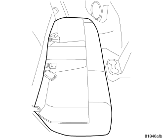
1. Release fuel system pressure. Refer to Fuel Pressure Release Procedure in this section.
2. Remove the air cleaner lid, disconnect the inlet air temperature sensor and makeup air hose.
3. Remove the negative battery cable.
4. Remove the rear seat cushion.
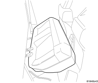
5. Rear seat cushion loose.
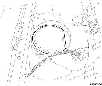
6. Remove plastic cover.
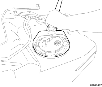
7. Clean top of tank to remove loose dirt and debris.
8. Use special tool Spanner Wrench #9340 to remove left side module lock ring.
NOTE: wrap shop towels around hoses to catch any gasoline spillage.
9. Disconnect electrical and fuel lines from module.
10. Drain fuel from tank.
11. Raise and support the vehicle.
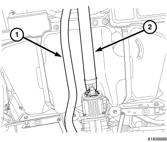
12. Remove exhaust system.
13. For All Wheel Drive vehicles, remove drive shaft.
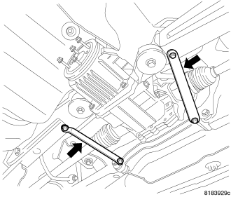
14. Remove stay bars.
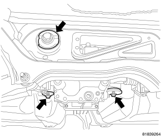
NOTE: For All Wheel Drive vehicles the rear driveline module must be lowered to remove fuel tank assembly.
15. Tie rear driveline module to suspension crossmember.
16. Support rear driveline module.
17. Remove 3 mounting bolts and lower rear drive line module from suspension crossmember.
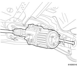
18. Module lowered.
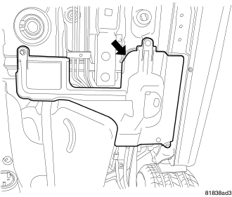
19. Remove splash shield.
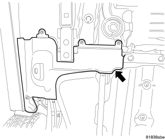
20. Remove splash shield.
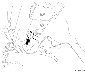
21. Disconnect vapor canister line.
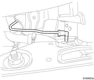
22. Disconnect filler tube recirculation vent line and purge line.
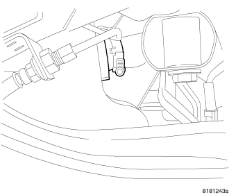
CAUTION: There may be fuel in the fill tube. Remove hose carefully to reduce fuel splash.
23. Disconnect fuel tank from rubber fill hose.
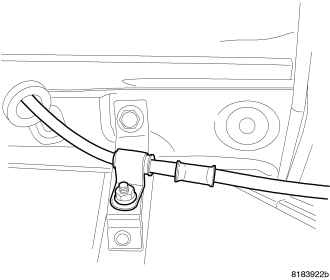
24. Remove parking brake cable mounting from fuel tank strap.
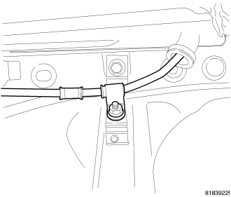
25. Remove parking brake cable mounting from fuel tank strap.
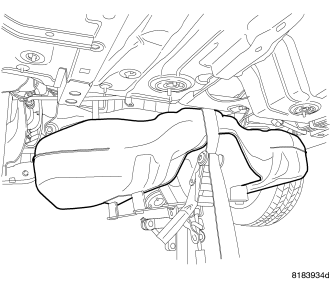
26. Support fuel tank.
27. Remove bolts from the fuel tank straps.
28. Remove fuel tank from vehicle.
INSTALLATION
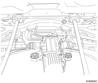
1. Install fuel tank straps.
2. Raise fuel tank into position.
3. Position fuel tank straps. Tighten fuel tank strap bolts to 47 N·m (34.5 ft. lbs.). Remove transmission jack. Ensure straps are not twisted or bent.
4. Install parking brake cable.
5. Install parking brake cable.
6. Connect filler tube recirculation vent line and purge line.
7. Connect fuel fill tube to tank inlet. Tighten hose clamp to 4.1 N·m (38 in. lbs.).
8. Connect vapor canister line.
9. Install rear driveline module, (Refer to 3 - DIFFERENTIAL & DRIVELINE/REAR DRIVELINE MODULE - INSTALLATION).
10. Install stay bars, (Refer to 3 - DIFFERENTIAL & DRIVELINE/REAR DRIVELINE MODULE - INSTALLATION).
11. Install splash shield.
12. Install splash shield.
13. Install exhaust system (1).
14. Install drive shaft (2), (Refer to 3 - DIFFERENTIAL & DRIVELINE/PROPELLER SHAFT - INSTALLATION).
15. While holding the pump module in position, install lock ring and use special tool Spanner Wrench #9340 to tighten lock ring.
16. Connect electrical connector and lock the connector.
17. Connect the fuel line. Refer to Quick Connect Fittings in this section.
18. Install plastic cover.
19. Install rear cushion.
20. Install the negative battery cable.
21. Install the air cleaner lid, connect the inlet air temperature sensor and makeup air hose.
22. Fill fuel tank with clean fuel. Use the Scan Tool to pressurize the system and check for leaks.