MODULE-REAR DRIVELINE
- STANDARD PROCEDURE - DRAIN AND FILL
- REMOVAL
- DISASSEMBLY
- ASSEMBLY
- INSTALLATION
- SPECIFICATIONS -
- SPECIAL TOOLS
STANDARD PROCEDURE - DRAIN AND FILL
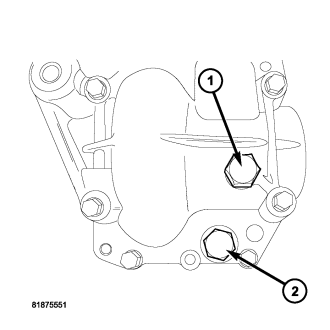
1. Remove fill plug (1) and drain plug (2). Drain fluid.
2. Install drain plug (2) and tighten to 32 N·m (24 ft.lb.).
3. Fill with MOPAR® MS9020 SAE 80W90 Gear Lube to bottom of fill plug.
4. Install fill plug (1) and tighten to 32 N·m (24 ft.lb.).
REMOVAL
1. Raise vehicle on a hoist.
2. Remove the rear tires.
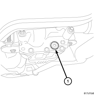
3. Remove the drain plug (1) and drain the fluid from the rear driveline module.
4. Remove the rear propeller shaft. (Refer to 3 - DIFFERENTIAL & DRIVELINE/PROPELLER SHAFT - REMOVAL)
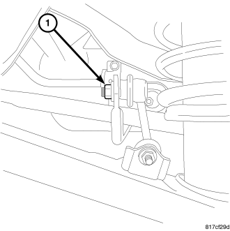
5. Remove right side sway bar nut (1) if equipped.
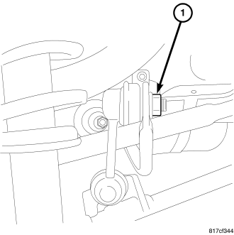
6. Remove left side sway bar nut (1) if equipped.

7. Roll sway bar (2) down and out of the way if equipped.
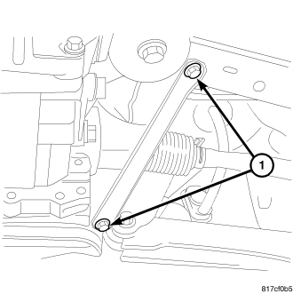
8. Remove the left side stay bracket bolts (1).
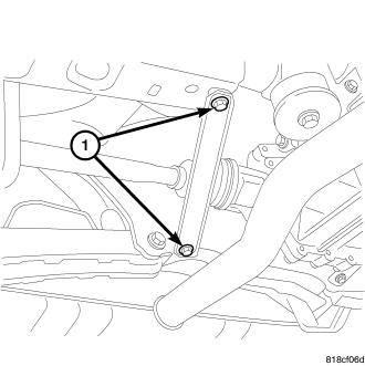
9. Remove the right side stay bracket bolts (1).
10. Remove the exhaust system up to the catalytic converter. (Refer to 11 - EXHAUST SYSTEM/MUFFLER - REMOVAL).
11. Support the rear driveline module with a transmission jack.
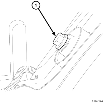
12. Remove the rear bolt (1) at the driveline module.
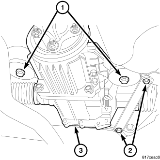
13. Remove the two side bolts (1) at driveline module (3).
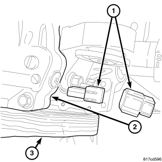
14. Lower driveline module enough to gain access to the electrical connector and bracket.
15. Remove the routing bracket bolt.
16. Unplug the electrical connector (1).
17. Remove breather hose off of ECC.
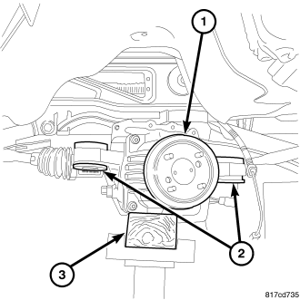
18. Lower the driveline module (1).
19. Disengage both halfshafts (2).
20. Remove driveline module.
21. Remove the ECC bolts.
22. Separate the ECC from the RDA.
DISASSEMBLY
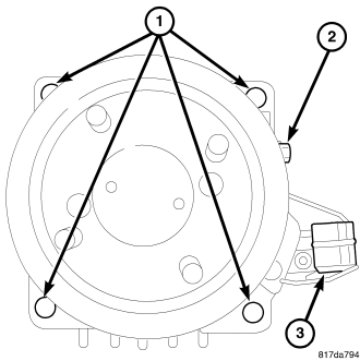
1. Remove the four bolts (1) holding the rear axle electric clutch.
2. Separate the rear axle electric clutch from the rear axle.
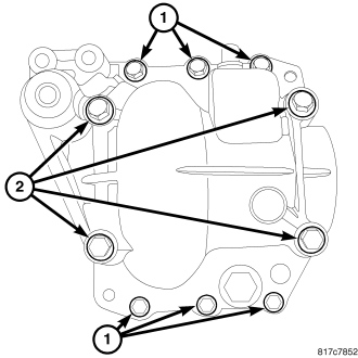
3. Remove the differential case bolts (1).
4. Remove the cap bolts (2).
5. Remove differential cover and both axle seals.
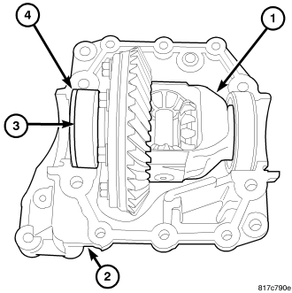
NOTE: There are select shims at each side of the carrier.
6. Remove the carrier (1) from the differential housing (2).
7. Measure the select shims on each side of the carrier roller bearings and note for installation.
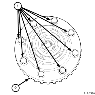
8. Remove the ring gear bolts (1).
9. Remove the ring gear (2).
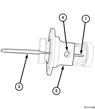
10. Remove roll pin (1) in carrier case (2) and through the pinion mate shaft (4) using a punch (3).
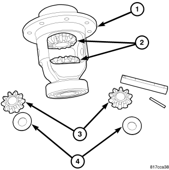
11. Remove spider gears (3), thrust washers (4) and side gears (2).
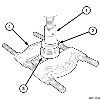
12. Remove carrier bearings (3) using Splitter 1130 (4), Installer 9643 (2) and a press (1).
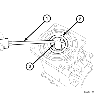
13. Use a screw driver to remove the pinion seal.
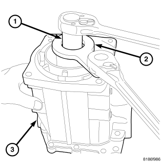
14. Remove pinion retaining nut using Spline Holder 9742 (1) and Socket 9921 (2).
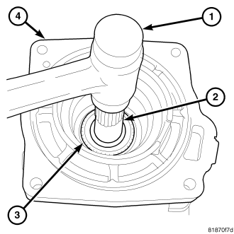
15. Tap pinion (3) with a soft hammer (1) to remove from case (4).
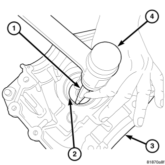
16. Using a hammer (4) and a punch (1) remove the outer pinion bearing cup (2)..
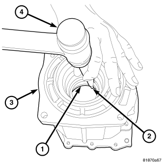
17. Using a hammer (4) and a punch (2) remove the pinion head bearing cup (1).
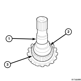
18. Remove collapsible spacer (2) from the pinion shaft (1).
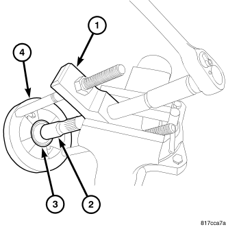
19. Remove the pinion bearing (3) using Puller C-293–PA (1) and Adapters C293–45 (2).
ASSEMBLY
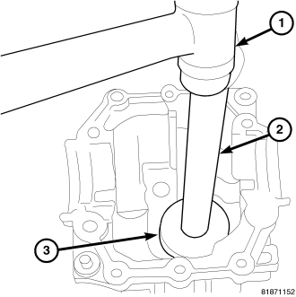
1. Install the pinion head bearing using Installer 5050A (3) and Handle C-4171 (2).
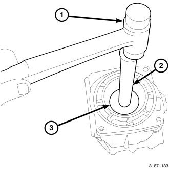
2. Install the outer pinion bearing cup using Installer 8594 and Handle C-4171.
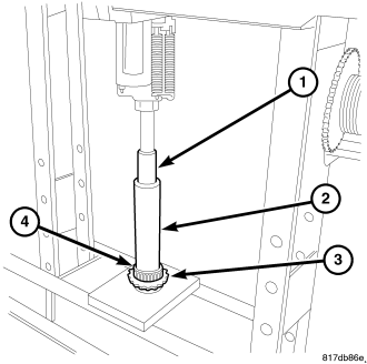
3. Install bearing (4) on pinion (3) using Installer 6052 (2) and press (1).
4. Install a new collapsible spacer (2) onto the pinion shaft (1).
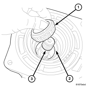
5. Install the pinion into the housing and place the outer bearing over the pinion.
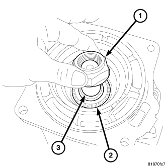
6. Install the pinion nut (1) onto the pinion shaft (3).
7. Using Spline Holder 9742 (1) and Socket 9921 (2), tighten pinion nut to 74 N·m (133 ft. lbs.).
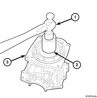
8. Install the pinion seal using Installer 9931 (2) and a hammer (1).
9. Install side gears (2), shims (4) and pinion gears (3) into carrier (1).
10. Install the pinion gear shaft into the pinion gears and start the roll pin .
11. Use a pin punch to install the roll pin (1).
12. Apply MOPAR© Lock & Seal Adhesive or an equivalent to the ring gear bolts (1) .
13. Install ring gear (2) onto the carrier.
14. Install ring gear bolts (1) and tighten to 41 N·m (30 ft. lbs.).
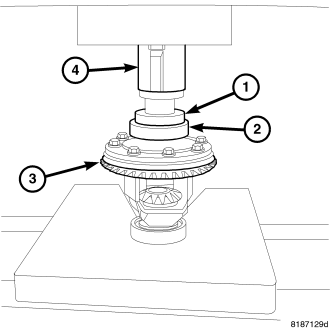
15. Press ring gear side (3) carrier bearing (2) onto shaft using Installer 9643 (1) and press (4).
16. Coat the ring and pinion gears with pattern grease before assembling.
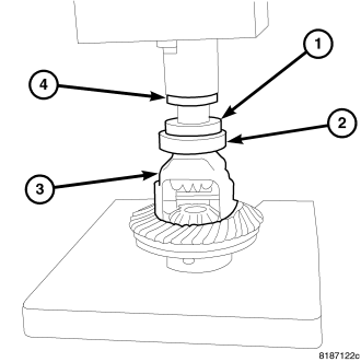
17. Press pinion gear side (3) carrier bearing (2) onto shaft using Installer 9643 (1) and press (4).
18. Install measured side shims (3) and carrier (1) into the carrier housing (2).
19. Apply a bead of MOPAR© AXLE RTV on the case to seal the cover.
20. Install cover onto carrier case.
21. Tighten cap bolts (2) to 48 N·m (35 ft. lbs.) and tighten cover bolts (1) to 23 N·m (16 ft. lbs.).
22. Open the window on the cover and do a pattern check of the gears.
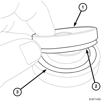
23. Place pinion side axle seal (1) onto Installer 9893 (3) with lip side down (2).
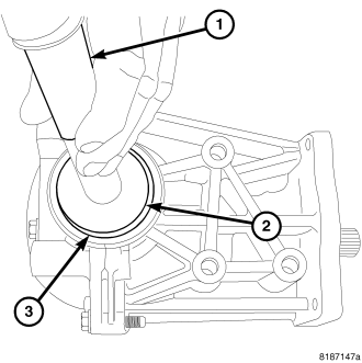
24. Install pinion side axle seal using Installer 9893 (2) and Handle C-4171 (1).
25. Place pinion side axle seal (1) onto Installer 9893 (3) with lip side down (2).
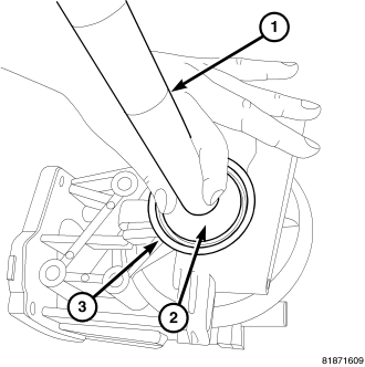
26. Install ring gear side axle seal using Installer 9893 (2) and Handle C-4171 (1).
27. Remove all old gasket material on the mating surfaces of the ECC and RDA. Coat the edge face with liquid gasket. Install wave washer.
28. Install the ECC to the RDA and tighten the bolts to 78 N·m (58 ft. lbs.).
INSTALLATION
1. Lift driveline module (1) with a transmission jack while installing both axles (2).
2. Connect breather hose to ECC.
3. Connect the electrical connector (1).
4. Install wire harness bracket and two mounting bolt and tighten to 10 N·m (89 in. lbs.).
5. Lift driveline module into place.
6. Install the two driveline module side mounting bolts (1) and tighten to 102 N·m (75 ft. lbs.).
7. Install the one rear driveline module mounting bolt (1) and tighten to 102 N·m (75 ft. lbs.).
8. Install right side stay bracket and tighten to bolts (1) 61 N·m (45 ft. lbs.)
9. Install left side stay bracket and tighten to bolts (1) to 61 N·m (45 ft. lbs.).
10. Install the propeller shaft (Refer to 3 - DIFFERENTIAL & DRIVELINE/PROPELLER SHAFT - INSTALLATION) .
11. Fill the rear axle with fluid.
12. Roll sway bar (2) into place if equipped.
13. Install left side sway bar nut (10 and tighten to 61 N·m (45 ft. lbs) (1) if equipped.
14. Install right side sway bar nut (1) and tighten to 61 N·m (45 ft. lbs) (1) if equipped.
15. Install the exhaust (Refer to 11 - EXHAUST SYSTEM/MUFFLER - INSTALLATION) .
16. Install the wheels (Refer to 22 - TIRES/WHEELS - DIAGNOSIS AND TESTING) .
SPECIFICATIONS -
DESCRIPTION |
N·m |
Ft. Lbs. |
In. Lbs. |
| Bolt, Harness Bracket |
10 |
- |
89 |
| Bolts, Driveline Module Side Mounting |
102 |
75 |
- |
| Bolt, Rear Driveline Module |
102 |
75 |
- |
| Bolts, Stay Bracket |
61 |
45 |
- |
| Nut, Sway Bar |
61 |
45 |
- |
| Nut, Pinion |
74 |
133 |
- |
| Bolts, Ring Gear |
41 |
30 |
- |
| Bolts, Carrier Cap |
48 |
35 |
- |
| Bolts, Differential Cover |
23 |
16 |
- |
| Bolts, ECC to RDA |
78 |
58 |
- |
SPECIAL TOOLS
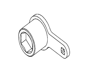
| OUTPUT SHAFT NUT SOCKET 9921 |
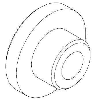
| INSTALLER 9643 |
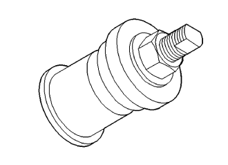
| Installer 5050A |
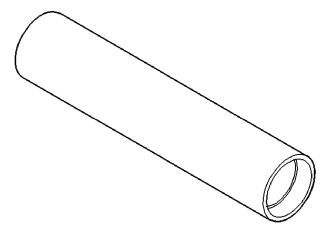
| Installer 6052 |
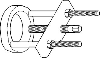
| Puller C-293-PA |
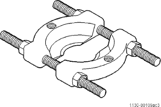
| SPLITTER 1130 |
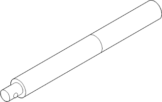
| Handle C- 4171 |
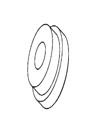
| INSTALLER 8594 |
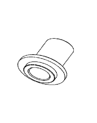
| INSTALLER 9931 |
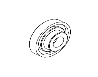
| INSTALLER 9893 |
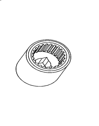
| SPLINE SCOCKET 9742 |