ASSEMBLY
HOUSING-HVAC
NOTE: LHD model with A/C shown in illustrations. RHD and heater-only models similar.
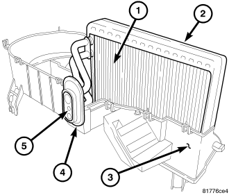
1. If removed, install the seal (4) onto the evaporator tube tapping block (5).
NOTE: Make sure that the foam insulator is properly positioned in the HVAC housing.
2. Carefully install the A/C evaporator (1) and foam insulator (2) into the lower half of the HVAC housing (3).
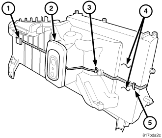
3. Install the two halves of the HVAC housing (4) together and engage the nine plastic retaining tabs (1). Make sure the retaining tabs are fully engaged.
4. Install the nine screws (3) and three metal clips (5) that secure the two halves of the HVAC housing together. Tighten the screws to 1.2 N·m (10 in lbs.). Make sure the metal clips are fully engaged to the housing halves.
5. Install the foam seal (2) onto the front of the two HVAC housing halves.
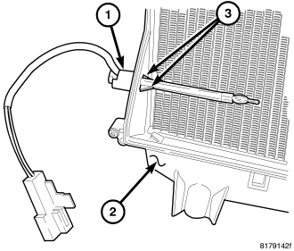
6. Install the evaporator temperature sensor (1) into the driver side of the HVAC housing (2) . Make sure the retaining tabs (3) are fully engaged to the housing.
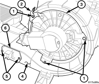
7. Position the blower motor (3) into the bottom of the HVAC housing (4).
8. Install the wire lead bracket (2) and the three screws (1) that secure the blower motor to the HVAC housing. Tighten the screws to 1.2 N·m (10 in. lbs.).
9. Position the blower motor resistor (6) into the HVAC housing.
10. Install the two screws (5) that secure the blower motor resistor to the HVAC housing. Tighten the screws to 1.2 N·m (10 in. lbs.).
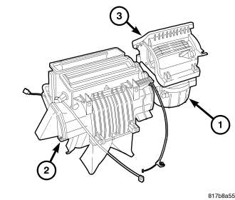
11. Install the air inlet housing (3) onto the HVAC housing (1) (refer to 24 - HEATING & AIR CONDITIONING/DISTRIBUTION/HOUSING-HVAC - HOUSING- AIR INLET - INSTALLATION).
12. Install the air distribution housing (2) onto the HVAC housing (refer to 24 - HEATING & AIR CONDITIONING/DISTRIBUTION/HOUSING-HVAC - HOUSING-AIR DISTRIBUTION - INSTALLATION).
NOTE: If the heater core is being replaced, flush the cooling system (refer to 7 - COOLING - STANDARD PROCEDURE - COOLING SYSTEM CLEANING/REVERSE FLUSHING).
13. Install the HVAC housing assembly (refer to 24 - HEATING & AIR CONDITIONING/DISTRIBUTION/HOUSING-HVAC - HOUSING-HVAC ASSEMBLY - INSTALLATION).
HOUSING-AIR DISTRIBUTION
NOTE: LHD model with A/C shown in illustrations. RHD and heater-only models similar.
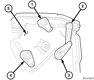
1. Install the four mode door levers (1, 2, 3 and 4) onto the right side of the air distribution housing (5) Make sure the lever retaining tabs are fully engaged to the housing.
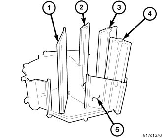
NOTE: Properly position the air doors within the air distribution housing by first aligning the four mode door levers to the scribe lines located on the right outer side of the air distribution housing. Then, install the air doors onto the mode door levers with the UP mark on each air door facing toward the top of the housing.
NOTE: If a seal on an air door is deformed or damaged, the air door must be replaced.
2. Align the four mode door levers to the scribe lines on the right outer side of the air distribution housing (5) and install the air door(s) (1, 2, 3 and 4) onto the mode door levers with the UP mark on each air door facing toward the top of the housing.
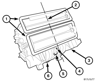
3. Align the air door(s) with the pivot shaft hole(s) in the air distribution housing (3) and install the two halves of the housing together. Make sure the three plastic retaining tabs (6) are fully engaged.
4. Install the five screws (4) and one metal clip (5) that secure the two halves of the air distribution housing together. Tighten the screws to 2.2 N·m (20 in lbs.). Make sure the metal clip is fully engaged to the housing halves.
NOTE: If any foam seal on the air distribution housing outlets is deformed or damaged, the seal must be replaced.
5. Inspect the foam seals (1), especially at the parting line (2). If a foam seal is deformed or damaged, it must be replaced.
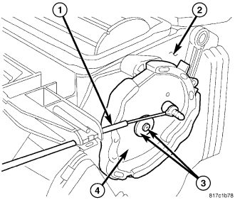
NOTE: Align the pins on the mode door levers with the grooves in the back of the mode door cam prior to installation of the cam.
6. Align the mode door levers on the right side of the air distribution housing (2) to the mode door cam (4) and install the cam onto the housing. Make sure the levers are correctly engaged to the cam.
7. Install the screw and washer (3) that secure the mode door cam to the air distribution housing. Tighten the screw to 0.6 N·m (5 in. lbs.).
8. Install the mode door cable (1) (refer to 24 - HEATING & AIR CONDITIONING/CONTROLS/CABLE-MODE DOOR - INSTALLATION).
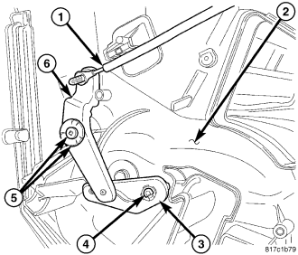
9. Install the blend door pivot lever (3) onto the end of the blend door pivot shaft (4) located on the left side of the air distribution housing (2). Make sure the lever retaining tab is fully engaged to the pivot shaft.
NOTE: Align the pin on the blend door lever with the groove in the pivot lever prior to installation of the blend door lever.
10. Install the blend door lever (6) onto the air distribution housing. Make sure the levers are correctly aligned to each other.
11. Install the screw and washer (5) that secure the blend door lever to the air distribution housing. Tighten the screw to 0.6 N·m (5 in. lbs.).
12. Install the temperature control cable (1) (refer to 24 - HEATING & AIR CONDITIONING/CONTROLS/CABLE-TEMPERATURE CONTROL - INSTALLATION).
13. If equipped with the 2.0L diesel engine, install the electric positive temperature coefficient (PTC) heater unit into the air distribution housing (refer to 24 - HEATING & AIR CONDITIONING/CABIN HEATER/HEATER UNIT - INSTALLATION).
14. Install the heater core into the air distribution housing (2) (Refer to 24 - HEATING & AIR CONDITIONING/PLUMBING/CORE HEATER - INSTALLATION).
15. Install the air distribution housing onto the HVAC housing (1) (refer to 24 - HEATING & AIR CONDITIONING/DISTRIBUTION/HOUSING-HVAC - HOUSING-AIR DISTRIBUTION - INSTALLATION).
16. Install the HVAC housing assembly (refer to 24 - HEATING & AIR CONDITIONING/DISTRIBUTION/HOUSING-HVAC - HOUSING-HVAC ASSEMBLY - INSTALLATION).
HOUSING-AIR INLET
NOTE: LHD model with A/C shown in illustrations. RHD and heater-only models similar.
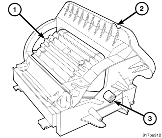
1. Carefully install the recirculation-air door (1) into the air inlet housing (2) by pinching the two ends of the air-door together and aligning the pivot shafts of the air-door to the pivot shaft holes in the air inlet housing.
NOTE: Install the recirculation door pivot shaft adapter by carefully pushing it straight into the end of the recirculation door pivot shaft.
2. Install the recirculation door pivot shaft adapter (3) into the right side pivot shaft of the recirculation air-door. Make sure the adapter is fully engaged to the pivot shaft.
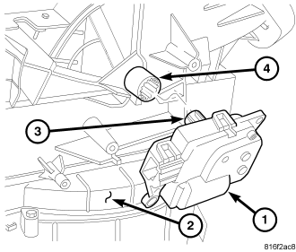
3. Install the recirculation door actuator (1) onto the right side of the air inlet housing (2). If necessary, rotate the actuator slightly to align the splines of the actuator output shaft (3) with those on the recirculation door pivot shaft adapter (4).
4. Install the air inlet housing (3) onto the HVAC housing (1) (refer to 24 - HEATING & AIR CONDITIONING/DISTRIBUTION/HOUSING-HVAC - HOUSING- AIR INLET - INSTALLATION).
5. Install the HVAC housing assembly (refer to 24 - HEATING & AIR CONDITIONING/DISTRIBUTION/HOUSING-HVAC - HOUSING-HVAC ASSEMBLY - INSTALLATION).