REMOVAL
- INTEGRATED CONTROL UNIT - GAS ENGINE
- INTEGRATED CONTROL UNIT - DIESEL ENGINE
- INTEGRATED CONTROL UNIT - RIGHT-HAND-DRIVE
INTEGRATED CONTROL UNIT - GAS ENGINE
NOTE: Before proceeding, (Refer to 5 - BRAKES - WARNING) (Refer to 5 - BRAKES - CAUTION).
1. Disconnect and isolate battery negative cable from battery post.
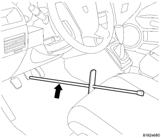
2. Using a brake pedal holding tool as shown, depress the brake pedal past its first 25 mm (1 inch) of travel and hold it in this position. This will isolate the master cylinder from the brake hydraulic system and will not allow the brake fluid to drain out of the master cylinder reservoir while the lines are disconnected.
3. Remove the engine appearance cover.
4. Loosen lower and upper mounting nuts, then remove the exhaust heat shield from the dash panel.
5. Pull the brake tube bundle routing clips (with tubes) loose from studs on the dash panel.
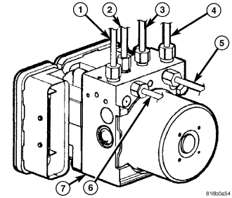
6. Remove the primary (4) and secondary (1) brake tubes (from master cylinder) at the hydraulic control unit (7).
7. Remove the remaining brake tubes (2, 3, 5, 6) at the hydraulic control unit (7).
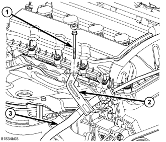
8. Remove the screw (1) fastening the power steering pressure hose routing clamp (2) to the exhaust manifold.
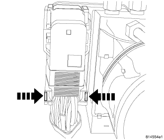
NOTE: Use this figure in the following step to release the ABM harness connector cover. It shows the location of the release tabs.
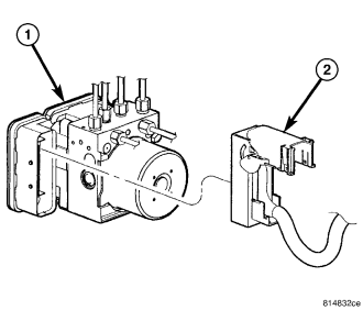
9. Disconnect the ABM harness connector from the Antilock Brake Module (ABM). To do so:
a. Depress the tabs on each side of the connector cover, then
b. Pull outward and upward on the lower half of the cover until it locks into position pointing straight outward (2). The connector can then be pulled straight outward off the ABM (1).
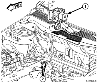
10. Loosen, but do not remove, the two mounting screws (2) attaching the ICU (1) mounting bracket to the body.
11. Lift the ICU and mounting bracket (1) off the mounting screws (2).
12. Move the brake tubes around as necessary without bending them and remove the ICU with bracket through the opening between the A/C lines and the exhaust manifold.
13. To separate the ABM from the HCU, (Refer to 5 - BRAKES/HYDRAULIC/MECHANICAL/ICU (INTEGRATED CONTROL UNIT) - DISASSEMBLY).
INTEGRATED CONTROL UNIT - DIESEL ENGINE
NOTE: Before proceeding, (Refer to 5 - BRAKES - WARNING) (Refer to 5 - BRAKES - CAUTION).
1. Disconnect and isolate battery negative cable from battery post.
2. Using a brake pedal holding tool as shown, depress the brake pedal past its first 25 mm (1 inch) of travel and hold it in this position. This will isolate the master cylinder from the brake hydraulic system and will not allow the brake fluid to drain out of the master cylinder reservoir while the lines are disconnected.
3. Raise and support the vehicle. (Refer to LUBRICATION & MAINTENANCE/HOISTING - STANDARD PROCEDURE)
4. Loosen, but do not remove, the two mounting screws (2) attaching the ICU (1) mounting bracket to the body.
5. Loosen the air inlet tube at the turbocharger.
6. Lower the vehicle.
7. Remove the engine appearance cover.
8. Loosen the air inlet tube at the air cleaner and engine cylinder head cover, then remove the tube.
9. Loosen lower and upper mounting nuts, then remove the heat shield from the dash panel.
10. Pull the brake tube bundle routing clips (with tubes) loose from studs on the dash panel.
11. Remove primary (4) and secondary (1) brake tubes (from master cylinder) at hydraulic control unit (7).
12. Remove remaining brake tubes (2, 3, 5, 6) at hydraulic control unit (7).
NOTE: Use this figure in the following step to release the ABM harness connector cover. It shows the location of the release tabs.
13. Disconnect the ABM harness connector from the Antilock Brake Module (ABM). To do so:
a. Depress the tabs on each side of the connector cover, then
b. Pull outward and upward on the lower half of the cover until it locks into position pointing straight outward (2). The connector can then be pulled straight outward off the ABM (1).
14. Lift the ICU and mounting bracket (1) off the mounting screws (2).
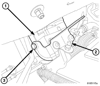
15. Rotate the ICU (1) around behind the engine until the bracket mounting screw (3) can be accessed.
16. Remove the ICU bracket mounting screw (3), then remove the bracket (2) from the ICU (1). The ICU has mounting pins that are inserted into grommets in the bracket that must be overcome to remove bracket.
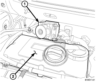
17. Remove the ICU (1) from the engine compartment out over the engine cylinder head cover (2).
18. To separate the ABM from the HCU, (Refer to 5 - BRAKES/HYDRAULIC/MECHANICAL/ICU (INTEGRATED CONTROL UNIT) - DISASSEMBLY).
INTEGRATED CONTROL UNIT - RIGHT-HAND-DRIVE
NOTE: Before proceeding, (Refer to 5 - BRAKES - WARNING) (Refer to 5 - BRAKES - CAUTION).
1. Disconnect and isolate battery negative cable from battery post.
2. Using a brake pedal holding tool as shown, depress the brake pedal past its first 25 mm (1 inch) of travel and hold it in this position. This will isolate the master cylinder from the brake hydraulic system and will not allow the brake fluid to drain out of the master cylinder reservoir while the lines are disconnected.
3. Remove the engine appearance cover.
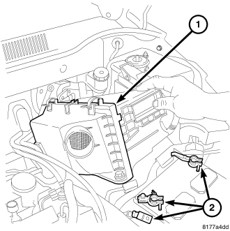
4. Remove the air cleaner housing (1). (Refer to 9 - ENGINE/AIR INTAKE SYSTEM/AIR CLEANER HOUSING - REMOVAL)
5. Remove the primary (4) and secondary (1) brake tubes (from master cylinder) at the Hydraulic Control Unit (HCU) (7).
6. Remove the remaining brake tubes (2, 3, 5, 6) at the HCU (7).
NOTE: Use this figure in the following step to release the Antilock Brake Module (ABM) harness connector cover. It shows the location of the release tabs.
7. Disconnect the ABM harness connector from the Antilock Brake Module (ABM). To do so:
a. Depress the tabs on each side of the connector cover, then
b. Pull outward and upward on the lower half of the cover until it locks into position pointing straight outward (2). The connector can then be pulled straight outward off the ABM (1).
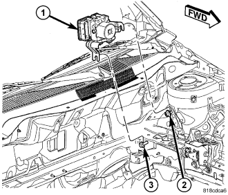
8. Loosen, but do not remove, the mounting nut (2) and screw (3) attaching the Integrated Control Unit (ICU) (1) mounting bracket to the body.
9. Lift the ICU and mounting bracket (1) off the mounting stud and screw.
10. To separate the ABM from the HCU, (Refer to 5 - BRAKES/HYDRAULIC/MECHANICAL/ICU (INTEGRATED CONTROL UNIT) - DISASSEMBLY).