T355 MANUAL TRANSAXLE
DESCRIPTION
This five speed is a constant-mesh manual transaxle. All gear ranges, except reverse, are synchronized. The reverse gear utilizes a reverse brake for shifting ease. The reverse idler gear is supported on a sliding spindle idler shaft. The transaxle case is aluminum with a steel end-plate bearing cover. It is housed in a die-cast aluminum case featuring a two-piece, middle split design.
The T355 transaxle internal components can be serviced only by separating the gear case from the bellhousing case.
CAUTION: The transaxle output shaft is serviced as a unit. No disassembly and reassembly is possible. Damage to the transaxle may result.
TRANSAXLE IDENTIFICATION
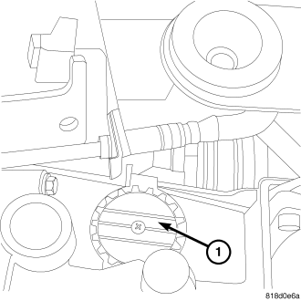
The transaxle model, assembly number, and build date are on a metal I.D. tag (1) that is attached to the top of the transaxle.
GEAR RATIOS
| GEAR |
|
| 1st |
3.77 |
| 2nd |
2.16 |
| 3rd |
1.41 |
| 4th |
1.026 |
| 5th |
0.81 |
| REVERSE |
3.4 |
| FINAL DRIVE RATIO |
4.12 |
| REVERSE BRAKE |
YES |
| CLUTCH RELEASE SYSTEM |
HYDRAULIC |
CAUTION: All gears and shafts must not be interchanged with other transaxles; they will not function correctly.
The differential is a conventional arrangement of gears that is supported by tapered roller bearings. The final output gear turns the ring gear and differential assembly, thereby turning the drive axle shafts.
GEARSHIFT PATTERN
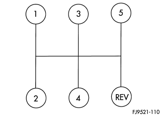
The T355 transaxle shift pattern is a modified H–pattern. Overdrive fifth and reverse gears are in-line and outboard of the first through fourth gear positions.
REMOVAL
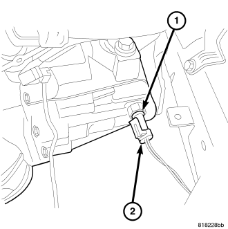
1. Raise hood.
2. Remove the resonator.
3. Remove engine cover.
4. Remove air cleaner assembly.
5. Disconnect both battery cables. (Refer to 8 - ELECTRICAL/BATTERY SYSTEM/BATTERY - REMOVAL)
6. Remove battery hold down clamp and bolt, and remove battery.
7. Remove battery tray. (Refer to 8 - ELECTRICAL/BATTERY SYSTEM/TRAY - REMOVAL)
8. Unplug the speed sensor connector (if equipped).
9. Disconnect back-up lamp switch connector (2).
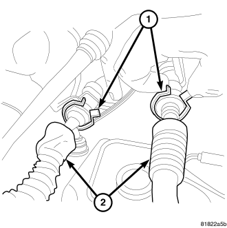
10. Remove shift cable-to-bracket clips (1).
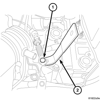
11. Disconnect shift selector and crossover cable (1) from levers. Remove cables and secure out of the way.
12. Remove the slave cylinder hose at bracket.
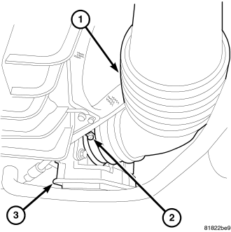
13. Remove the air inlet tube (1) by loosing the screw (2) at the throttle body (3).
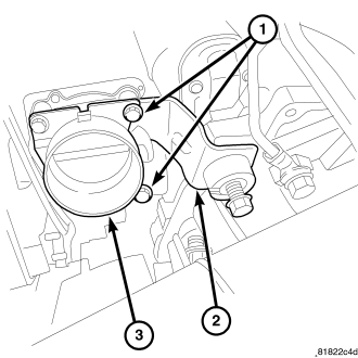
14. Remove the throttle body support bracket bolts (1).
15. Remove the throttle body support bracket (2).
16. Remove upper bell housing bolts.
17. Remove the starter bolts and slide the starter back. (Refer to 8 - ELECTRICAL/STARTING/STARTER MOTOR - REMOVAL)
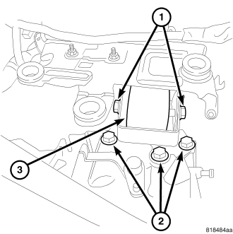
18. Support transmission and remove the upper transmission mount through bolt (1).
19. Raise vehicle on hoist.
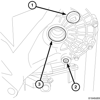
20. Remove transaxle oil drain plug (2) and drain oil into a suitable container. Reinstall drain plug and tighten to 14 N·m (120 in. lbs.).
21. Remove both axle halfshafts (Refer to 3 - DIFFERENTIAL & DRIVELINE/HALF SHAFT - REMOVAL).
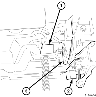
22. Support the engine with a screw jack (1).
23. Remove bell housing dust cover (3).
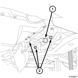
24. Remove four modular clutch-to-drive plate bolts (1). While removing bolts, one tight-tolerance (slotted) drive plate hole will be encountered. When this bolt is removed, mark drive plate and modular clutch assembly at this location, and be sure to align marks upon reassembly.
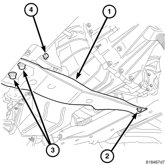
25. Remove the front transmission mount through bolt (4).
26. Remove the transmission crossmember mounting bolts (2, 3).
27. Remove the transmission crossmember (1).
28. Install a transmission jack (2).
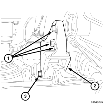
29. Remove the rear transmission through bolt (3).
30. Remove the rear transmission mount bolts (1) and mount (2).
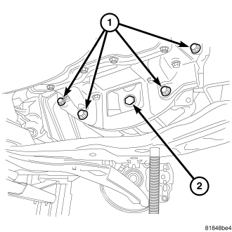
31. Remove the remaining transmission bell housing bolts (1).
32. Carefully lower engine and transaxle on screw jack and transmission jack until proper removal clearance is obtained.
33. Obtain a helper to assist in holding transaxle while removing transaxle-to-engine mounting bolts.
34. Remove transaxle from vehicle.
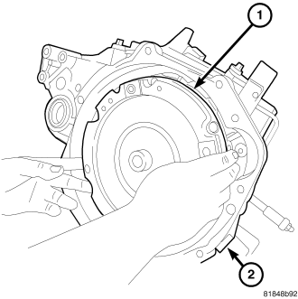
35. Remove clutch module from transaxle input shaft (1).
36. If installing a new or replacement transaxle, remove the upper mount (3), transfer to the replacement unit and tighten all bolts (2) to 62 N·m (45 ft. lbs.).
DISASSEMBLY
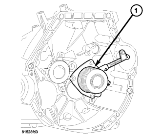
1. Remove bolts from slave cylinder-to-clutch bellhousing and remove slave cylinder (1) from transaxle.
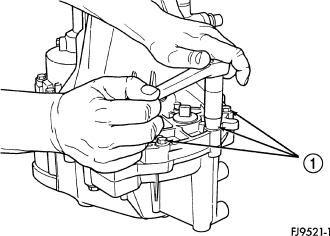
The T355 transaxle internal components can be serviced only by separating the gear case from the bellhousing case.
CAUTION: The transaxle output shaft is serviced as a unit. No disassembly and reassembly is possible. Damage to the transaxle may result.
2. Place transaxle on bench.
3. Remove transaxle case half bolts (1).
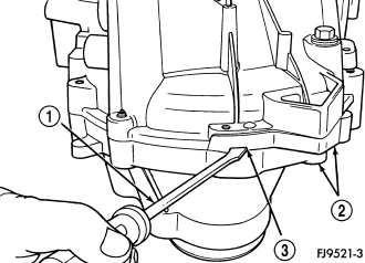
4. Place two screwdrivers (1) into the slots (3) provided in the case halves (2) near the dowels. Separate the case halves.
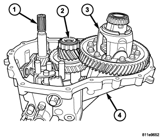
5. Remove bellhousing half from gear case half (4).
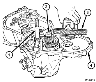
6. Remove differential assembly (3) from housing (4).

NOTE: The reverse idler shaft bolt has an O-ring that should be replaced during assembly.
7. Remove reverse idler shaft bolt (3).
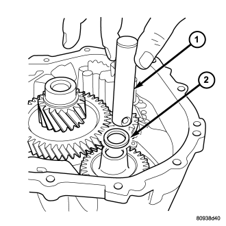
8. Remove reverse idler shaft (1).
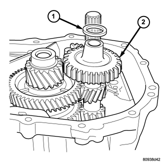
9. Remove reverse idler gear (2) and spacer (1).
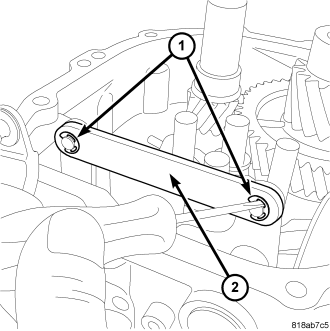
10. Remove the clips (1) at the linkage tie bar (2).
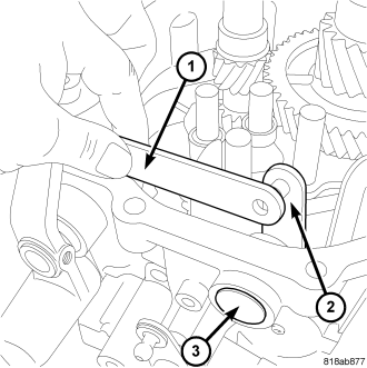
11. Remove the linkage tie bar (1).
12. Remove the plug (3) at the selector shaft (2).
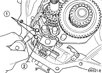
13. Remove two screws (1) retaining reverse fork bracket (2).
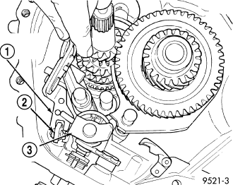
14. Remove reverse fork bracket (1) and reverse cam block-out assembly (2).
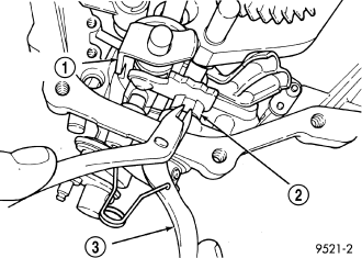
15. Using snap–ring pliers (3), remove link shaft spacer (2).
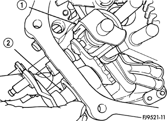
16. Pull the link shaft shift pin out of the slot in the blocker assembly. Turn selector shaft (2) up and out of the way.
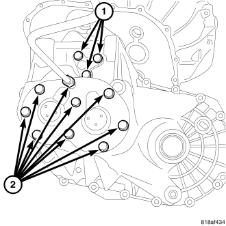
17. Remove transaxle end cover (2) and shift fork bolts (1).
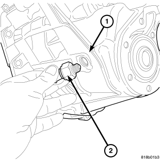
18. Remove the backup lamp switch (2).
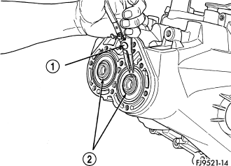
19. Remove two snap rings (2) retaining the output shaft and the input shaft to the bearings.
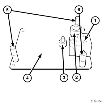
20. The bench fixture (4) and adaptors 9761-1 (1), 9761-2 (3), 9761-3 (2), 9761-6 (5) and 9761-7 (6) will be used to remove input and output shafts from the case.
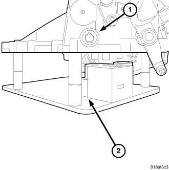
21. Turn transaxle over. Install transaxle (1) onto bench fixture (2). Verify shim spacers and adaptors are in position on bench fixture. Install transaxle into shop press.
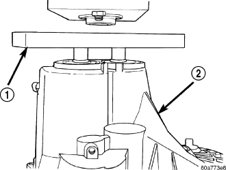
22. Install bearing fixture 6768 (1) onto transaxle end bearings. Verify tool is properly aligned to input and output shafts.
CAUTION: The oil dams in the input and output shafts can be damaged while pressing on the shafts if the bearing fixture is not used properly.
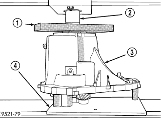
23. Install transaxle gear case (3) into shop press. Press (2) output and input shaft assemblies out of case.
24. Remove transaxle from press.
25. Carefully remove transaxle case (1) from the shaft assemblies and bench fixture (2).
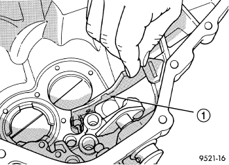
26. Be sure the oil–feed trough (1) to the end bearings is not damaged.
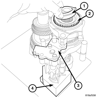
27. Remove the reverse brake friction cone (1) from the input shaft assembly.
28. Remove the blocking ring (2) from the input shaft assembly.
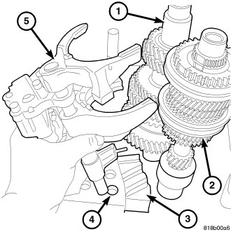
29. Remove the shift blocker assembly and the 1-2 shift fork (5) from the bench fixture (4).
30. Remove input (2) and output shaft (1) assemblies from bench fixture 6785.
CAUTION: The output shaft assembly is serviced as an assembly. Do not try to repair any component on the output shaft. If the 1-2 synchronizer or gear fails, it is necessary to replace the complete output shaft assembly.
CLEANING
Clean the gears, bearings, shafts, synchronizers, thrust washers, oil feeder, shift mechanism, gear case, and bellhousing with solvent. Dry all parts except the bearings with compressed air. Allow the bearings to either air dry or wipe them dry with clean shop towels.
INSPECTION
Inspect the gears, bearings, shafts and thrust washers. Replace the bearings and cups if the rollers are worn, chipped, cracked, flat spotted, brinnelled, or if the bearing cage is damaged or distorted. Replace the thrust washers if cracked, chipped, or worn. Replace the gears if the teeth are chipped, cracked or worn thin. Inspect the synchronizers. Replace the sleeve if worn or damaged in any way. Replace the stop rings if the friction material is burned, flaking off, or worn. Check the condition of the synchro keys and springs. Replace these parts if worn, cracked, or distorted.
ASSEMBLY
The T355 transaxle internal components can be serviced only by separating the gear case from the bellhousing case.
CAUTION: The transaxle output shaft is serviced as a unit. No disassembly and reassembly is possible. Damage to the transaxle may result.
The sealant used to seal the transaxle case halves is MOPAR® Gasket Maker, Loctite® 518, or equivalent. The sealant used for the bearing end plate cover is MOPAR® RTV.
1. Load bench fixture (4) with adaptors 9761-1 (1), 9761-2 (3), 9761-3 (2), 9761-4 (5) and 9761-5 (6).
2. Install the output (1) and input (2) shafts onto bench fixture 6785.
3. Install shift blocker assembly and the 1-2 shift fork (5) onto the bench fixture (4).
NOTE: Adaptor 9761-1 will slide shift blocker assembly and the 1-2 shift fork into the input and output shafts.
4. Align all shift forks and slide into place.
5. Install reverse brake blocking ring (2).
6. Install reverse brake friction cone (1).
NOTE: One shift fork bolt may need to be installed to align assembly.
7. Install gear–case half (1) over bench fixture (2). Line up shift finger over 3-4 lug.
8. Line up reverse brake friction cone lugs to the slots in the gear case. Verify reverse brake shim is in position.
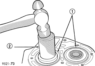
9. Position input and output bearings (1) on the shafts. Using Seal Installer C-4992-1 (2), install input and output shaft bearings (1) until they bottom into the case and against the shafts.
10. Installnew snap rings (2) at input and output bearings.
11. Apply MOPAR® RTV sealant to end–cover outer edge and around bolt holes. Install end–cover onto gear case. Tighten end cover bolts to 25 N·m (225 in. lbs.).
NOTE: Install new O-rings on shift blocker assembly bolts.
12. Install the three shift blocker assembly bolts (1) and tighten to 25 N·m (225 in. lbs.).
13. Remove gear case from bench fixture.
14. Install gear case in a holding fixture with end cover facing down.
15. Turn selector link (2) into slot on blocker assembly.
16. Push selector link spacer clip onto selector shaft. Install shift levers.
17. Install reverse idler gear (2) and spacer (1).
18. Install reverse idler shaft (1).
NOTE: Install a new O-ring on reverse idler shaft bolt.
19. Install bolt into reverse idler shaft (2) and tighten to 26 N·m (19 ft. lbs.).
20. Install reverse fork bracket (1).
21. Tighten reverse fork bracket (1) screws to 11 N·m (96 in. lbs.).
22. Install the linkage tie bar (1).
23. Install the linkage tie bar clips (1).
24. Install differential (3) into gear case (4).
BEARING ADJUSTMENT PROCEDURE
1. Use extreme care when removing and installing bearing cups and cones. Use only an arbor press for installation, as a hammer may not properly align the bearing cup or cone. Burrs or nicks on the bearing seat gives a false end–play reading while gauging for proper shims. Improperly seated bearing cups and cones are subject to low–mileage failure.
2. Bearing cups and cones should be replaced if they show signs of pitting or heat distress. If distress is seen on either the cup or bearing rollers, both cup and cone must be replaced.
3. Bearing preload and drag torque specifications must be maintained to avoid premature bearing failures. Used (original) bearings may lose up to 50% of the original drag torque after break–in. All bearing adjustments must be made with no other component interference or gear intermesh.
4. Replace bearings as a pair: If one differential bearing is defective, replace both differential bearings, if one input shaft bearing is defective, replace both input shaft bearings.
5. Bearing cones must not be reused if removed.
6. Turning–torque readings should be obtained while smoothly rotating in either direction.
DIFFERENTIAL BEARING PRELOAD ADJUSTMENT
NOTE: True bearing turning–torque readings can be obtained only with the geartrain removed from the case.
1. Remove bearing cup and existing shim from clutch bellhousing case.
2. Press in new bearing cup into bellhousing case (or use a cup that has been ground down on the outer edge for ease of measurement).
3. Press in new bearing cup into gear case side.
4. Oil differential bearings with transmission fluid. Install differential assembly in transaxle gear case. Install clutch bellhousing over gear case. Install and tighten case bolts to 25 N·m (225 in. lbs.).
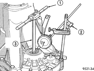
5. Position transaxle with bellhousing facing down on workbench with C-clamps. Position dial indicator.
NOTE: Position of dial indicator is for illustrative purposes only. The dial indicator should be parallel to T-Handle to obtain the most accurate reading.
6. Apply a medium load to differential with Torque Tool C-4995 (3) and a T-handle (1), in the downward direction. Roll differential assembly back and forth a number of times. This will settle the bearings. Zero the dial indicator (2). To obtain end play readings, apply a medium load in an upward direction while rolling differential assembly back and forth. Record end play.
7. The shim required for proper bearing preload is the total of end play, plus (constant) preload of 0.18mm (0.007 in.). Never combine shims to obtain the required preload.
8. Remove case bolts. Remove clutch bellhousing differential bearing cup. Install shim(s) selected in.Then press the bearing cup into clutch bellhousing.
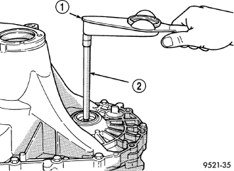
9. Install clutch bellhousing. Install and tighten case bolts to 25 N·m (225 in. lbs.). Using Torque Tool C-4995 (2) and an inch-pound torque wrench (1), check turning torque of the differential assembly. The turning torque should be 6 to 12 in. lbs. If the turning torque is too high, install a 0.05 mm (0.002 inch) thinner shim. If the turning torque is too low, install a 0.05 mm (0.002 inch) thicker shim.
10. Recheck turning torque (1). Repeat until the proper turning torque is obtained.
Once proper turning torque has been established, place gear case on the end plate. Draw a bead of MOPAR® Gasket Maker, Loctite® 518, or equivalent, on the flat surface of the case mating flange. Install clutch bellhousing onto gear case. Install and tighten case bolts to 25 N·m (225 in. lbs.).
25. Install the backup lamp switch (2), tighten switch to 23 N·m (17 ft. lbs.).
26. Install slave cylinder (1) to transaxle using new bolts (Refer to 6 - CLUTCH/SLAVE CYLINDER - INSTALLATION).
INSTALLATION
1. Install clutch module (1) (if equipped) onto input shaft.
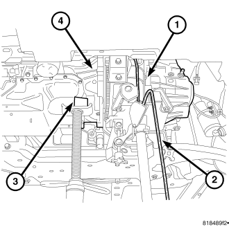
2. Install transaxle (1) into position.
3. Install the transmission crossmember and tighten to 68 N·m (50 ft. lbs.).
4. Install the rear transmission mount through bolt (4) at this time and tighten to 68 N·m (50 ft. lbs.).
5. Install transaxle-to-engine mounting bolts and tighten to 48 N·m (35 ft. lbs.).
6. Raise engine and transaxle with screw jack and transmission jack until upper mount bracket aligns with upper mount. Install mount bolts (1) and tighten to 68 N·m (50 ft. lbs.).
7. Remove screw jack.
8. Install four (4) modular clutch-to-driveplate bolts (4). Align drive plate and modular clutch alignment marks placed upon disassembly. Start with tight-tolerance (slotted) hole, install and torque bolts to 88 N·m (65 ft. lbs.).
9. Install starter motor and tighten bolts to 54 N·m (40 ft. lbs.). Make sure to fasten ground cable to upper starter bolt. (Refer to 8 - ELECTRICAL/STARTING/STARTER MOTOR - INSTALLATION)
10. Install bell housing dust cover.
11. Install both front axle driveshafts (Refer to 3 - DIFFERENTIAL & DRIVELINE/HALF SHAFT - INSTALLATION).
12. Fill transaxle with suitable amount of fluid (2.7 liters) (Refer to 21 - TRANSMISSION/TRANSAXLE/MANUAL/FLUID - STANDARD PROCEDURE).
13. Lower the vehicle.
14. Install the remaining bell housing bolts and tighten to 8 N·m (35 ft. lbs.).
15. Connect the hydraulic clutch slave cylinder (1). An audible click should be heard. Verify connection by pushing and pulling quick connect.
16. Connect shift and selector cables (2) to shift lever. Install cables to bracket (1).
17. Connect back-up lamp switch connector (1).
18. Connect the vehicle speed sensor connector if equipped.
19. Install battery tray.
20. Install battery and tighten, hold down clamp to secure battery.
21. Install the air cleaner assembly.
22. Connect the battery cables.
23. Road test vehicle and inspect for leaks.
SPECIAL TOOLS
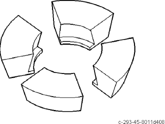
| Adapter Blocks C-293-45 |
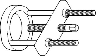
| PULLER C-293-PA |
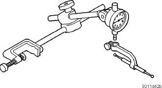
| Dial Indicator C-3339 |
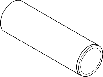
| Sleeve C-3717 |
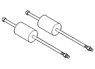
| Slide Hammer C-3752 |
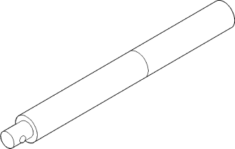
| Universal Handle C-4171 |
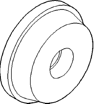
| Bearing Installer C-4628 |
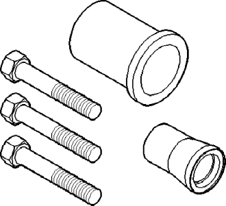
| Seal Remover C-4680 |
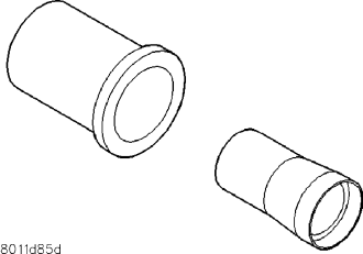
| Seal Installer C-4992 |
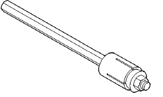
| Torque Tool C-4995 |
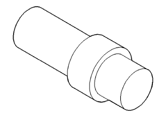
| Adapter C-4996 |
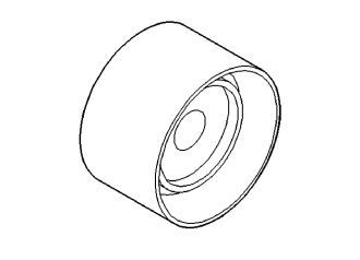
| Installer L-4410 |
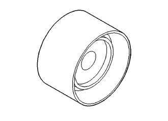
| Installer L-4440 |
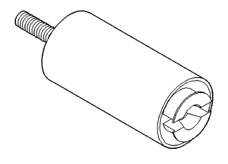
| Puller L-4518 |
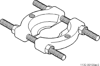
| Bearing Splitter 1130 |
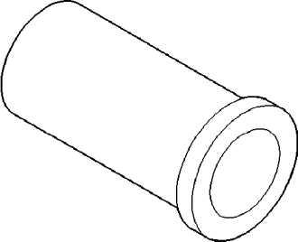
| Driver 6342 |
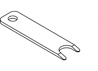
| Disconnect Tool 6638A |
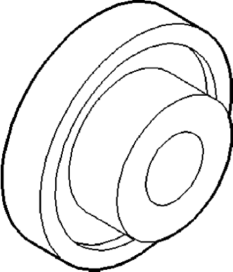
| Seal Installer 9928 |
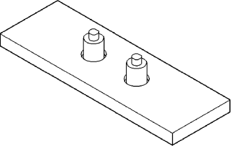
| Bearing Remover 6768 |
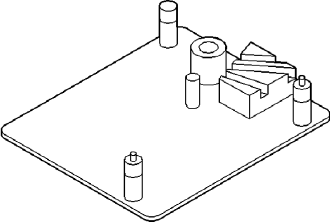
| Bench Fixture 6785 |
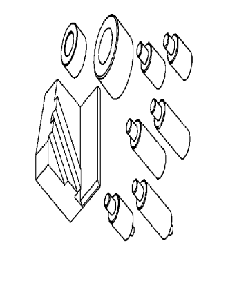
| ADAPTORS 9761 |
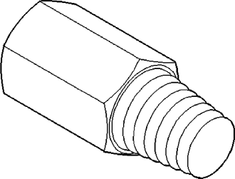
| Remover 6786 |
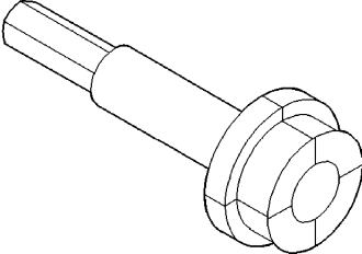
| Remover 6787 |
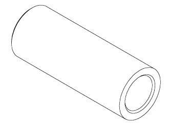
| Installer, 8864 |
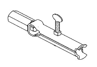
| PULLER 9585 |
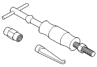
| SLIDE HAMMER C-637 |
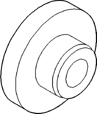
| Installer, Bearing - 5064 |
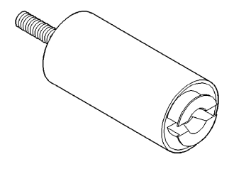
| Puller- L-4518 |
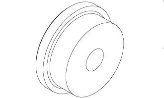
| INSTALLER 8692 |