LOWER BALL JOINT
REMOVAL
1. Remove the tire and wheel assembly.
2. Remove the brake caliper and rotor (Refer to 5 - BRAKES/HYDRAULIC/MECHANICAL/ROTORS - REMOVAL).
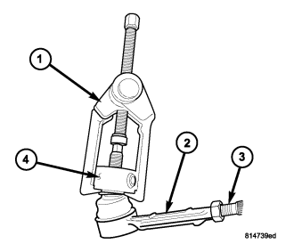
3. Disconnect the tie rod (2) from the steering knuckle (4) using special tool C-3894-A (1) (Refer to 19 - STEERING/LINKAGE/TIE ROD END - REMOVAL).
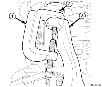
4. Separate the upper ball joint (2) from the knuckle (3) using special tool 8677 (1).
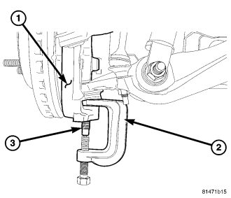
5. Separate the lower ball joint (3) from the steering knuckle (1) using special tool 8677 (2).
6. Remove the steering knuckle (Refer to 2 - SUSPENSION/FRONT/KNUCKLE - REMOVAL).
7. Remove the clevis bracket and move the halfshaft to the side and support the halfshaft out of the way 4X4 only (Refer to 2 - SUSPENSION/FRONT/CLEVIS BRACKET - REMOVAL).
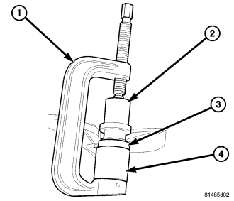
NOTE: Extreme pressure lubrication must be used on the threaded portions of the tool. This will increase the longevity of the tool and insure proper operation during the removal and installation process .
8. Press the ball joint from the lower control arm (3) using special tools C-4212-F (PRESS) (1), C–4212–3 (Driver) (2) and 9654–3 (Receiver) (4).
INSTALLATION
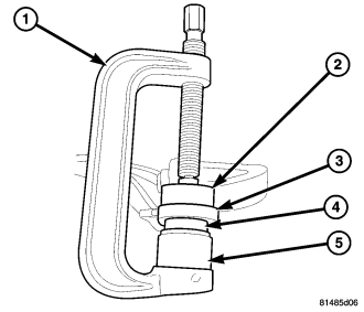
NOTE: Extreme pressure lubrication must be used on the threaded portions of the tool. This will increase the longevity of the tool and insure proper operation during the removal and installation process .
1. Install the ball joint (4) into the control arm (3) and press in using special tools C-4212-F (press) (1), 9654–1 (Driver) (5) and 9654–2 (Receiver) (2).
2. Stake the ball joint flange in four evenly spaced places around the ball joint flange, using a chisel and hammer.
3. Remove the support for the halfshaft and install into position, then install the clevis bracket. 4X4 only (Refer to 2 - SUSPENSION/FRONT/CLEVIS BRACKET - INSTALLATION).
4. Install the steering knuckle (Refer to 2 - SUSPENSION/FRONT/KNUCKLE - INSTALLATION).
5. Install the tie rod end into the steering knuckle (Refer to 19 - STEERING/LINKAGE/TIE ROD END - INSTALLATION).
6. Install and tighten the halfshaft nut to 251 N·m (185 ft. lbs.). (If Equipped).
7. Install the brake caliper and rotor (Refer to 5 - BRAKES/HYDRAULIC/MECHANICAL/ROTORS - INSTALLATION).
8. Install the tire and wheel assembly (Refer to 22 - TIRES/WHEELS/WHEELS - STANDARD PROCEDURE).
9. Check the vehicle ride height (Refer to 2 - SUSPENSION/WHEEL ALIGNMENT - STANDARD PROCEDURE).
10. Perform a wheel alignment (Refer to 2 - SUSPENSION/WHEEL ALIGNMENT - STANDARD PROCEDURE).