TURBOCHARGER
DESCRIPTION
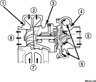
| Turbocharger Operation |
| 1 - TURBINE SECTION |
| 2 - EXHAUST GAS |
| 3 - BEARING HOUSING |
| 4 - COMPRESSOR SECTION |
| 5 - INLET AIR |
| 6 - COMPRESSED AIR TO ENGINE |
| 7 - EXHAUST GAS |
| 8 - EXHAUST GAS TO EXHAUST PIPE |
CAUTION: The turbocharger is a performance part and must not be tampered with. The wastegate bracket is an integral part of the turbocharger. Tampering with the wastegate components can reduce durability by increasing cylinder pressure and thermal loading due to incorrect inlet and exhaust manifold pressure. Poor fuel economy and failure to meet regulatory emissions laws may result. Increasing the turbocharger boost WILL NOT increase engine power.
The turbocharger is an exhaust-driven supercharger which increases the pressure and density of the air entering the engine through the charge air cooler. With the increase of air entering the engine, more fuel can be injected into the cylinders, which creates more power during combustion.
The turbocharger assembly consists of four (5) major component systems
- Turbine section
- Compressor section
- Bearing housing
- Variable veins
- Actuator
OPERATION
Exhaust gas pressure and energy drive the turbine, which in turn drives a centrifugal compressor that compresses the inlet air, and forces the air into the engine through the charge air cooler and plumbing. Since heat is a by-product of this compression, the air must pass through a charge air cooler to cool the incoming air and maintain power and efficiency.
Increasing air flow to the engine provides:- Improved engine performance
- Lower exhaust smoke density
- Improved operating economy
- Altitude compensation
- Noise reduction.
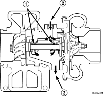
The turbocharger is lubricated by engine oil that is pressurized, cooled, and filtered. The oil is delivered to the turbocharger by a supply line (2) that is tapped into the engine block. The oil travels into the bearing housing, where it lubricates the shaft (1) and bearings . A return pipe (3) at the bottom of the bearing housing, routes the engine oil back to the crankcase.
The most common turbocharger failure is bearing failure related to repeated hot shutdowns with inadequate “cool-down” periods. A sudden engine shut down after prolonged operation will result in the transfer of heat from the turbine section of the turbocharger to the bearing housing. This causes the oil to overheat and break down, which causes bearing and shaft damage the next time the vehicle is started.
Letting the engine idle after extended operation allows the turbine housing to cool to normal operating temperature. The following chart should be used as a guide in determining the amount of engine idle time required to sufficiently cool down the turbocharger before shut down, depending upon the type of driving and the amount of cargo.
| TURBOCHARGER "COOL DOWN" CHART | |||
| Driving | Load | Turbocharger | Idle Time (in minutes) |
| Condition | Temperature | Before Shut Down | |
| Stop & Go | Empty | Cool | Less than 1 |
| Stop & Go | Medium | Warm | 1 |
| Highway Speeds | Medium | Warm | 2 |
| City Traffic | Max. GCWR | Warm | 3 |
| Highway Speeds | Max. GCWR | Warm | 4 |
| Uphill Grade | Max. GCWR | Hot | 5 |
REMOVAL
1. Disconnect negative battery cable.
2. Remove engine cover (Refer to 9 - ENGINE - REMOVAL).
3. Disconnect the MAF and Inlet air pressure sensors wiring harness connectors, disconnect the air outlet duct from the turbocharger, and remove air cleaner assembly (Refer to 9 - ENGINE/AIR INTAKE SYSTEM/AIR CLEANER HOUSING - REMOVAL).
4. Remove charge air cooler inlet hose from turbocharger (Refer to 11 - EXHAUST SYSTEM/TURBOCHARGER SYSTEM/CHARGE AIR COOLER AND PLUMBING - REMOVAL).
5. Drain cooling system.
6. Remove coolant recovery pressure container (Refer to 7 - COOLING/ENGINE/COOLANT RECOVERY PRESS CONTAINER - REMOVAL) .
7. Disconnect the turbocharger actuator vacuum hose and position aside.
8. Remove turbocharger upper heat shield.
9. Raise and support the vehicle.
10. Remove the lower splash shield.
11. Disconnect the front exhaust pipe from the turbocharger.
12. Remove the turbocharger support bracket.
13. Disconnect turbocharger oil return line at turbocharger .
14. Lower the vehicle.
15. Remove the turbocharger oil supply line.
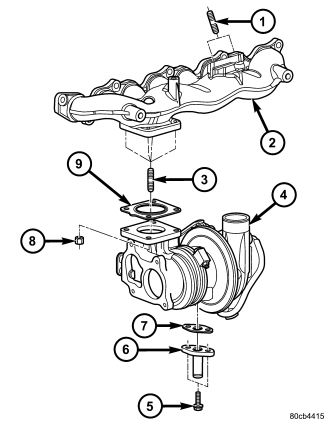
16. Remove turbocharger to exhaust manifold retaining nuts and separate turbocharger from exhaust manifold.
CLEANING
All old gaskets should be inspected for any tears or signs of prior leakage. If any gaskets show such indications, they should be replaced with new gaskets. All gasket mating surfaces must be cleaned of old gasket material to produce a smooth and dirt free sealing surface for the new gasket.
INSTALLATION
1. Connect turbocharger to exhaust manifold with new gasket. Torque retaining nuts to 32 N·m.
NOTE: After Tightening The Exhaust Manifold To Specification Using a Diagonal-Cross Pattern, Retrace The Pattern Checking The Correct Torque Value Again.
2. Install exhaust manifold and turbocharger assembly with new gasket in position on studs in cylinder head . Install retaining nuts and torque to 36 N·m.
3. Install thermostat housing (Refer to 7 - COOLING/ENGINE/ENGINE COOLANT THERMOSTAT - INSTALLATION).
4. Install viscous heater (Refer to 24 - HEATING & AIR CONDITIONING/PLUMBING/ELECTRIC COOLANT PUMP - INSTALLATION) .
5. Install accessory drive belt (Refer to 7 - COOLING/ACCESSORY DRIVE/DRIVE BELTS - INSTALLATION) .
6. Raise vehicle on hoist.
7. Connect turbocharger oil return line at turbocharger.
8. Connect exhaust pipe at turbocharger downpipe.
9. Lower vehicle from hoist.
10. Connect oil supply line at turbocharger . Torque banjo fitting to 24 N·m.
11. Install exhaust manifold heat shield . Torque retaining bolts to 24 N·m (18 lbs.ft.).
12. Reposition EGR cooler and or EGR valve assembly on exhaust manifold . Torque retaining nuts and bolt to 32.4N·m.
13. Connect EGR pipe to EGR valve. Torque bolts to 32 N·m.
14. Connect EGR cooler coolant hoses at cooler (2.8L).
15. Install coolant recovery pressure container (Refer to 7 - COOLING/ENGINE/COOLANT RECOVERY PRESS CONTAINER - INSTALLATION).
16. Refill cooling system (Refer to 7 - COOLING/ENGINE - STANDARD PROCEDURE) .
17. Connect charge air cooler inlet hose at turbocharger.
18. Install air cleaner assembly.
19. Connect air inlet hose to turbocharger.
20. Install engine cover (Refer to 9 - ENGINE - INSTALLATION).
21. Connect negative battery cable.