BATTERY
DESCRIPTION
CONVENTIONAL BATTERY - GASOLINE ENGINES
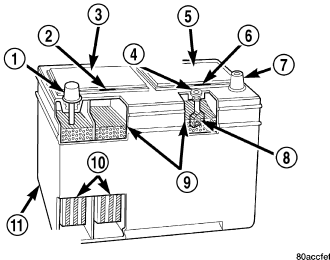
A conventional large capacity, low-maintenance storage battery (11) is standard factory-installed equipment on models equipped with a gasoline engine. (Refer to 8 - ELECTRICAL/BATTERY SYSTEM - SPECIFICATIONS) for the proper specifications of the factory-installed batteries available on this model. Male post type terminals (1) and (7) made of a soft lead material protrude from the top of the molded plastic battery case to provide the means for connecting the battery to the vehicle electrical system. The battery positive terminal post (1) is physically larger in diameter than the negative terminal post (7) to ensure proper battery connection. The letters POS and NEG are also molded into the top of the battery case adjacent to their respective positive and negative terminal posts for identification confirmation. (Refer to 8 - ELECTRICAL/BATTERY SYSTEM/CABLES - DESCRIPTION) for more information on the battery cables that connect the battery to the vehicle electrical system.
The battery is made up of six individual cells that are connected in series. Each cell contains positively charged plate groups (10) that are connected with lead straps to the positive terminal post, and negatively charged plate groups (10) that are connected with lead straps to the negative terminal post. Each plate consists of a stiff mesh framework or grid coated with lead dioxide (positive plate) or sponge lead (negative plate). Insulators or plate separators made of a non-conductive material are inserted between the positive and negative plates to prevent them from contacting or shorting against one another. These dissimilar metal plates are submerged in a sulfuric acid and water solution called an electrolyte.
SPIRAL PLATE BATTERY - DIESEL ENGINE
WARNING: Never exceed 14.4 volts when charging a spiral plate battery. Personal injury and/or battery damage may result.
Vehicles equipped with a diesel engine utilize a spiral wound plate designed battery with recombination technology. This is a maintenance-free battery that is capable of delivering more power than a conventional battery. This additional power is required by a diesel engine during cold cranking.
Spiral plate technology takes the elements of traditional batteries - lead and sulfuric acid - to the next level. By tightly winding layers of spiral grids and acid-permeated vitreous separators into cells, the manufacturer has developed a battery with more power and service life than conventional batteries the same size. The spiral plate battery is completely, permanently sealed. Through gas recombination, hydrogen and oxygen within the battery are captured during normal charging and reunited to form the water within the electrolyte, eliminating the need to add distilled water. Therefore, these batteries have non-removable battery vent caps. Water cannot be added to this battery.
The acid inside an spiral plate battery is bound within the vitreous separators, ending the threat of acid leaks. This feature allows the battery to be installed in any position anywhere in the vehicle.
Spiral plate technology is the process by which the plates holding the active material in the battery are wound tightly in coils instead of hanging flat, like conventional batteries. This design has a lower internal resistance and also increases the active material surface area.
Due to the maintenance-free design, distilled water cannot be added to this battery. Therefore, if more than 14.4 volts are used during the spiral plate battery charging process, water vapor can be exhausted through the pressure-sensitive battery vents and lost for good. This can permanently damage the spiral plate battery. Never exceed 14.4 volts when charging a spiral plate battery. Personal injury and/or battery damage may result.
Batteries are used to store electrical energy potential in a chemical form. When an electrical load is applied to the battery terminals, an electrochemical reaction occurs within the battery. This reaction causes the battery to discharge electrical current.
OPERATION
The battery is designed to store electrical energy in a chemical form. When an electrical load is applied to the terminals of the battery, an electrochemical reaction occurs. This reaction causes the battery to discharge electrical current from its terminals. As the battery discharges, a gradual chemical change takes place within each cell. The sulfuric acid in the electrolyte combines with the plate materials, causing both plates to slowly change to lead sulfate. At the same time, oxygen from the positive plate material combines with hydrogen from the sulfuric acid, causing the electrolyte to become mainly water. The chemical changes within the battery are caused by the movement of excess or free electrons between the positive and negative plate groups. This movement of electrons produces a flow of electrical current through the load device attached to the battery terminals.
As the plate materials become more similar chemically, and the electrolyte becomes less acid, the voltage potential of each cell is reduced. However, by charging the battery with a voltage higher than that of the battery itself, the battery discharging process is reversed. Charging the battery gradually changes the sulfated lead plates back into sponge lead and lead dioxide, and the water back into sulfuric acid. This action restores the difference in the electron charges deposited on the plates, and the voltage potential of the battery cells. For a battery to remain useful, it must be able to produce high-amperage current over an extended period. A battery must also be able to accept a charge, so that its voltage potential may be restored.
The battery is vented to release excess hydrogen gas that is created when the battery is being charged or discharged. However, even with these vents, hydrogen gas can collect in or around the battery. If hydrogen gas is exposed to flame or sparks, it may ignite. If the electrolyte level is low, the battery may arc internally and explode. If the battery is equipped with removable cell caps, add distilled water whenever the electrolyte level is below the top of the plates. If the battery cell caps cannot be removed, the battery must be replaced if the electrolyte level becomes low.
REMOVAL
WARNING: Wear a suitable pair of rubber gloves (not the household type) when removing a battery by hand. Safety glasses should also be worn. If the battery is cracked or leaking, the electrolyte can burn the skin and eyes.
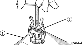
NOTE: The use of a battery terminal puller (2) may be necessary if the cable clamps will not separate from the battery posts.
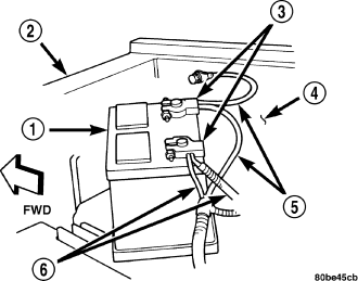
1. Turn the ignition switch to the Off position. Be certain that all electrical accessories are turned off.
2. Loosen the battery negative cable (5) terminal clamp pinch-bolt hex nut.
3. Disconnect the battery negative cable (5) terminal clamp from the battery negative terminal post. If necessary, use a battery terminal puller to remove the terminal clamp from the battery post.
4. Loosen the battery positive cable (6) terminal clamp pinch-bolt hex nut.
5. Disconnect the battery positive cable (6) terminal clamp from the battery positive terminal post. If necessary, use a battery terminal puller to remove the terminal clamp from the battery post.
6. Remove the battery holddowns from the battery, (Refer to 8 - ELECTRICAL/BATTERY SYSTEM/BATTERY HOLDDOWN - REMOVAL) for the proper battery holddown removal procedures.
7. Remove the battery and the battery thermal guard (if equipped) from the battery tray as a unit.
8. If equipped, remove the battery thermal guard from the battery case.
INSTALLATION
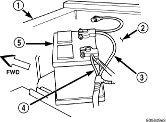
1. Clean and inspect all of the battery system components. (Refer to 8 - ELECTRICAL/BATTERY SYSTEM - CLEANING) and (Refer to 8 - ELECTRICAL/BATTERY SYSTEM - INSPECTION) for the proper procedures.
2. If equipped, install the battery thermal guard onto the battery case (5).
3. Position the battery (5) onto the battery trayt. Ensure that the battery positive and negative terminal posts are correctly positioned. The battery cable terminal clamps must reach the correct battery terminal post without stretching the cables.
4. Reinstall the battery holddowns onto the battery, (Refer to 8 - ELECTRICAL/BATTERY SYSTEM/BATTERY HOLDDOWN - INSTALLATION) for the proper installation procedure.
CAUTION: Be certain that the battery cable terminal clamps are connected to the correct battery terminal posts. Reversed battery polarity may damage electrical components of the vehicle.
5. Clean the battery cable terminal clamps and the battery terminal posts. (Refer to 8 - ELECTRICAL/BATTERY SYSTEM - CLEANING) for cleaning procedure.
6. Reconnect the battery positive cable (4) terminal clamp to the battery positive terminal post. Tighten the terminal clamp pinch-bolt hex nut to 8.5 N·m (75 in. lbs.).
7. Reconnect the battery negative cable (3) terminal clamp to the battery negative terminal post. Tighten the terminal clamp pinch-bolt hex nut to 8.5 N·m (75 in. lbs.).
8. Apply a thin coating of petroleum jelly or chassis grease to the exposed surfaces of the battery cable terminal clamps and the battery terminal posts.
9. Obtain an appropriate scan tool and check the PCM for any stored battery disconnect trouble codes. Clear codes if required.