COVER-CYLINDER HEAD
DESCRIPTION
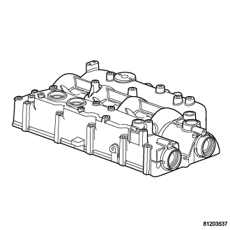
The cylinder head cover and the intake manifold on this engine are made of cast aluminum. The cylinder head cover also incorporates a oil drain back hole for the crankcase ventilation (CCV) system.
REMOVAL
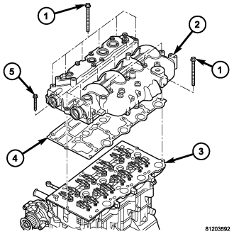
CAUTION: Before removing the cylinder head cover/intake manifold (2) the witness mark on the crankshaft hub must rotated to the 3 O'clock position or, 90° after TDC to assure proper alignment of the camshafts and the crankshaft. Failure to do so could result in valve and/or piston damage during reassembly.
1. Disconnect negative battery cable.
2. Remove engine cover and bracket (Refer to 9 - ENGINE - REMOVAL).
3. Remove the air cleaner housing (Refer to 9 - ENGINE/AIR INTAKE SYSTEM/AIR CLEANER HOUSING - REMOVAL).
4. Drain cooling system (Refer to 7 - COOLING/ENGINE/COOLANT - STANDARD PROCEDURE).
5. Evacuate the air conditioning.
6. Disconnect the coolant recovery hose at the radiator.
7. Remove the charge air inlet hose at the coolant module.
8. Remove the upper radiator hose at the radiator.
9. Separate the A/C hoses from the cooling fan shroud.
10. Remove cooling fan and fan drive viscous drive assembly, along with the fan shroud (Refer to 7 - COOLING/ENGINE/FAN DRIVE VISCOUS CLUTCH - REMOVAL).
11. Remove accessory drive belt (Refer to 7 - COOLING/ACCESSORY DRIVE/DRIVE BELTS - REMOVAL) .
12. Remove cooling fan support (Refer to 7 - COOLING/ENGINE/RADIATOR FAN - REMOVAL).
13. Disconnect the EGR cooler pipe behind the inner timing cover.
14. Remove generator (Refer to 8 - ELECTRICAL/CHARGING/GENERATOR - REMOVAL), and generator rear support bracket.
15. Remove the accessory drive belt Idler pulleys L.H.Thread.
16. Remove the drive belt tensioner.
17. Remove the power steering pump pulley.
18. Remove the vibration damper.
CAUTION: Before removing the cylinder head cover/intake manifold (2) the witness mark on the crankshaft hub must rotated to the 3 O'clock position or, 90° after TDC to assure proper alignment of the camshafts and the crankshaft. Failure to do so could result in valve and/or piston damage during reassembly.
19. Rotate the crankshaft hub to 90° after TDC (3 O'clock position).
20. Remove heater hose pipe fasteners.
NOTE: It may be necessary to rotate the camshaft gear bolt slightly to gain proper camshaft alignment pin seating against the intake manifold. Alignment pins must seat flush against the intake manifold.
21. Install the intake camshaft locking pin VM.1052 and exhaust camshaft locking pin VM.1053 (Refer to 9 - ENGINE/VALVE TIMING - STANDARD PROCEDURE).
22. Remove outer timing belt cover (Refer to 9 - ENGINE/VALVE TIMING/TIMING BELT / CHAIN COVER(S) - REMOVAL).
23. Remove timing belt (Refer to 9 - ENGINE/VALVE TIMING/TIMING BELT/CHAIN AND SPROCKETS - REMOVAL).
24. Install special tool VM.1085 and remove camshaft gears.
25. Remove timing belt idler pulleys L.H.Thread.
26. Remove inner timing belt cover (Refer to 9 - ENGINE/VALVE TIMING/TIMING BELT / CHAIN COVER(S) - REMOVAL).
27. Disconnect coolant temperature sensor, camshaft position sensor, boost pressure/intake air temperature sensor, fuel injectors, fuel temperature sensor, fuel rail solenoid, and EGR air flow electrical connectors.
28. Disconnect the main engine harness connectors at the right inner fender well and position the harness over the left side of the engine and aside.
29. Disconnect the brake booster vacuum pipe from the EGR air control valve.
30. Disconnect the EGR cooler pipe from the EGR air control valve.
31. Separate the main engine harness from the bracket on the EGR air control valve.
32. Remove the EGR tube from the underside of the EGR air control valve.
33. Separate the block heater wiring harness from the oil level indicator tube.
34. Remove the oil level indicator tube from the EGR air control valve.
35. Remove fuel injectors (Refer to 14 - FUEL SYSTEM/FUEL INJECTION/FUEL INJECTOR - REMOVAL).
36. Remove fuel rail (Refer to 14 - FUEL SYSTEM/FUEL DELIVERY/FUEL RAIL - REMOVAL).
37. Disconnect oil separator outlet hose at separator.
38. Remove the oil separator from the intake manifold/cylinder head cover (2).
39. Disconnect the return fuel junction block from the intake manifold/cylinder head cover (2).
40. Remove cylinder head cover/intake manifold retaining bolts (1).
41. Lift cylinder head cover/intake manifold (2) from cylinder head (3).
NOTE: When removing rocker arm and lifter assemblies, Always keep lifters in an upright position and in the order that they were removed from the cylinder head (3).
42. Remove rocker arm and lifter assemblies from cylinder head (3).
43. Remove cylinder head cover/intake manifold gasket (4) from cylinder head (3).
INSTALLATION
1. Clean and inspect sealing surfaces.
2. Install new gasket on cylinder head.
NOTE: Add a small amount of grease to the top of each valve to assist with rocket arm positioning.
3. Install rocker arm and lifter assemblies in cylinder head. Be sure to put rocker arm and lifter assemblies in same location as removed.
CAUTION: Care must be taken when installing the cylinder head cover/intake manifold. Do not knock the rocker arms off of the valves when installing the cover.
4. Install cylinder head cover/intake manifold.
NOTE: Be sure to lubricate cylinder head cover/intake manifold retaining bolts with engine oil before assembly. If new bolts are being installed, DO NOT lubricate before assembly.
5. Install two cylinder head cover/intake manifold retaining bolts and tighten finger tight.
6. Remove alignment studs and install remaining retaining bolts. Tighten retaining bolts finger tight.
7. Torque cylinder head cover/intake manifold retaining bolts following procedure below.
CYLINDER HEAD COVER/INTAKE MANIFOLD TIGHTENING PROCEDURE
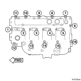
- Alternate between bolts #11 and #16 to seat cylinder head cover/intake manifold on cylinder head. Torque bolts to 7 N·m.
- Torque all cylinder head cover/intake manifold retaining bolts to 25 N·m in numerical order starting with #1 and ending with #16.
8. Connect EGR tube at intake manifold inlet tube. Torque clamp to 10.8 N·m.
9. Install turbo inlet tube retaining bolt at intake manifold. Torque bolt to 27.5 N·m.
10. Connect oil separator outlet hose at separator.
11. Install oil level indicator tube retaining bolt at intake manifold inlet. Torque bolt to 10 N·m.(88 in. lbs.).
12. Install brake booster vacuum tube retaining bolt at intake manifold inlet. Torque bolt to 10 N·m.(88 in. lbs.).
13. Install power steering pump reservoir in bracket.
14. Install fuel rail (Refer to 14 - FUEL SYSTEM/FUEL DELIVERY/FUEL RAIL - INSTALLATION).
15. Install fuel injectors and fuel injector supply lines (Refer to 14 - FUEL SYSTEM/FUEL INJECTION/FUEL INJECTOR - INSTALLATION).
16. Connect camshaft position sensor, boost pressure/intake air temperature sensor, EGR solenoid, and fuel pressure sensor electrical connectors.
17. Install inner timing belt cover (Refer to 9 - ENGINE/VALVE TIMING/TIMING BELT / CHAIN COVER(S) - INSTALLATION).
18. Install timing belt (Refer to 9 - ENGINE/VALVE TIMING/TIMING BELT/CHAIN AND SPROCKETS - INSTALLATION).
19. Install outer timing belt cover (Refer to 9 - ENGINE/VALVE TIMING/TIMING BELT / CHAIN COVER(S) - INSTALLATION).
20. Remove crankshaft VM.1089 and both camshaft locking pins (VM.1052,VM1053) (Refer to 9 - ENGINE/VALVE TIMING - STANDARD PROCEDURE).
21. Install vibration damper.
22. Install generator (Refer to 8 - ELECTRICAL/CHARGING/GENERATOR - INSTALLATION).
23. Install cooling fan support (Refer to 7 - COOLING/ENGINE/RADIATOR FAN - INSTALLATION).
24. Install accessory drive belt (Refer to 7 - COOLING/ACCESSORY DRIVE/DRIVE BELTS - INSTALLATION).
25. Install cooling fan and fan drive viscous clutch assembly (Refer to 7 - COOLING/ENGINE/FAN DRIVE VISCOUS CLUTCH - INSTALLATION).
26. Refill cooling system (Refer to 7 - COOLING/ENGINE/COOLANT - STANDARD PROCEDURE).
27. Install engine cover and bracket (Refer to 9 - ENGINE - INSTALLATION) .
28. Connect negative battery cable.