PAN-OIL
REMOVAL
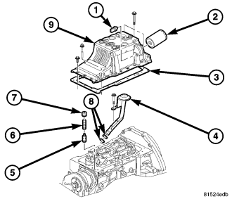
1. Disconnect negative battery cable.
2. Remove engine cover (Refer to 9 - ENGINE - REMOVAL).
NOTE: When installing engine support fixture, care must be taken not to damage the hood ajar switch mounted to the right inner fender.
3. Install engine support fixture, special tool #8534.
4. Raise vehicle on hoist.
5. Remove both front wheel and tire assemblies.
6. Remove front skid plate (if equipped).
7. Drain engine oil.
8. Disconnect the front drive shaft from the front drive axle,
9. Loosen both engine mount through bolts.
10. Lower vehicle.
11. Raise engine using support fixture, special tool #8534, until the viscous fan almost touches the fan shroud.
12. Raise vehicle on hoist.
13. Support the front cradle assembly with a suitable lifting device.
14. Mark the front cradle to under body position to assure proper alignment during assembly.
15. Remove both inner rail cradle alignment bolts in the front wheel housing.
16. Loosen both power steering gear retaining bolts, leave the retaining nuts on the bolts.
17. Loosen power steering lines from cradle.
18. Remove both lower front strut bolts.
19. Loosen both front cradle mounting bolts.
20. Loosen both rear cradle mounting bolts.
21. Disconnect the oil sending unit harness connector.
22. Remove all oil pan retaining bolts, separate the oil level indicator tube from the pan and lower oil pan (9).
23. Lower front cradle using the suitable lifting device until enough clearance is obtained to remove the oil pan (9).
INSTALLATION
1. Clean oil pan and sealing surfaces. Inspect oil pan and engine block.
2. Install oil pan, gasket, oil pan retaining bolts, hand tight..
3. Push the oil pan against adaptor plate and tighten transmission to oil pan bolts first.
4. Tighten oil pan bolts to 11.8N·m (104 lbs.in.), beginning with the center bolts and then tighten the remaining bolts in a clockwise rotation. Retighten the center two bolts again after all bolts are tighten to specification.
5. Raise the front cradle using a suitable lifting devise and align the cradle with the underbody marks made during the removal procedure.
6. Torque the cradle mounting bolts to 122 N·m (90 lbs. ft.).
7. Torque the inner rail mounting bolts to 47 N·m (35 lbs. ft.).
8. Torque the steering gear mounting bolts to 162N·m (120 lbs. ft.).
9. Remove the cradle support devise and lower the vehicle.
10. Lower the engine using support fixture, special tool #8534, until the engine mount through bolts are seated in the cradle.
11. Raise the vehicle.
12. Torque engine mount through bolts to 88N·m (65 lbs. ft.).
13. Install front axle assembly (Refer to 3 - DIFFERENTIAL & DRIVELINE/FRONT AXLE - INSTALLATION).
14. Install front axle skid plate (if equipped) (Refer to 13 - FRAME & BUMPERS/FRAME/FRONT SKID PLATE - INSTALLATION).
15. Install both front wheel and tire assemblies (Refer to 22 - TIRES/WHEELS/WHEELS - STANDARD PROCEDURE) tighten to 115–155 N·m (85–115 lbs. ft.).
NOTE: When removing engine support fixture, care must be taken not to damage the hood ajar switch mounted to the right inner fender well (if equipped).
16. Lower the vehicle and remove the engine support fixture.
17. Refill engine to proper level with the correct viscosity engine oil.
18. Connect negative battery cable.
19. Start engine and inspect for leaks.
20. Install engine cover (Refer to 9 - ENGINE - INSTALLATION).
21. Perform complete front wheel alignment (Refer to 2 - SUSPENSION/WHEEL ALIGNMENT - STANDARD PROCEDURE).