REMOVAL
4WD
1. Siphon the power steering fluid from the power steering reservoir.
NOTE: The steering column on vehicles with an automatic transmission may not be equipped with an internal locking shaft that allows the ignition key cylinder to be locked with the key. Alternative methods of locking the steering wheel for service will have to be used.
2. Lock the steering wheel to prevent spinning of the clockspring.
3. Raise and support the vehicle.
4. Remove the skid plate from under the front end to gain access to the gear (Refer to 13 - FRAME & BUMPERS/FRAME/FRONT SKID PLATE - REMOVAL).
5. Remove the front tire and wheel assemblies.
NOTE: Mark the alignment adjusting cams for easier installation.
6. Remove the lower control arms. (Refer to 2 - SUSPENSION/FRONT/LOWER CONTROL ARM - REMOVAL).
7. Remove the front axle. (Refer to 3 - DIFFERENTIAL & DRIVELINE/FRONT AXLE - REMOVAL).
8. Remove the tie rod end nuts.
9. Separate tie rod ends from the knuckles with Puller C-3894-A.
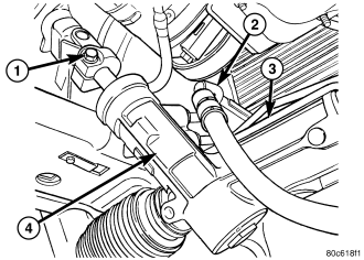
10. Remove the intermediate shaft lower coupler pinch bolt (1) and slide the coupler off the gear .
11. Remove the power steering lines (2) from the gear (4).
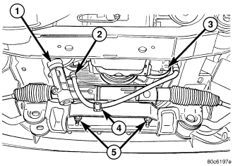
12. Remove the mounting bolts (5) from the gear to the front cradle .
13. Remove the steering gear (1) from the vehicle.
2WD
1. Siphon the power steering fluid from the power steering reservoir.
NOTE: The steering column on vehicles with an automatic transmission may not be equipped with an internal locking shaft that allows the ignition key cylinder to be locked with the key. Alternative methods of locking the steering wheel for service will have to be used.
2. Lock the steering wheel to prevent spinning of the clockspring.
3. Raise and support the vehicle.
4. Remove the skid plate from under the front end to gain access to the gear (Refer to 13 - FRAME & BUMPERS/FRAME/FRONT SKID PLATE - REMOVAL).
5. Remove the tire and wheel assembly.
NOTE: Mark the alignment adjusting cams and tie rod end jam nuts on the steering gear for easier installation.
6. Remove the tie rod end nuts.
7. Separate tie rod ends from the knuckles with Puller C-3894-A.
8. Remove the lower intermediate shaft coupler pinch bolt (1) and slide the coupler off the gear (4) .
9. Remove the power steering lines (2) from the gear (1).
10. Remove the mounting bolts (5) from the gear (1) to the front cradle .
11. Remove the steering gear (1) from the vehicle.
DIESEL
1. Siphon the power steering fluid from the power steering reservoir.
NOTE: The steering column on vehicles with an automatic transmission may not be equipped with an internal locking shaft that allows the ignition key cylinder to be locked with the key. Alternative methods of locking the steering wheel for service will have to be used.
2. Lock the steering wheel to prevent spinning of the clockspring.
3. Raise and support the vehicle.
4. Remove the skid plate from under the front end to gain access to the gear (Refer to 13 - FRAME & BUMPERS/FRAME/FRONT SKID PLATE - REMOVAL)
5. Remove the tire and wheel assembly.
NOTE: Mark the alignment adjusting cams for easier installation.
6. Remove the lower control arms. (Refer to 2 - SUSPENSION/FRONT/LOWER CONTROL ARM - REMOVAL).
7. Remove the front axle. (Refer to 3 - DIFFERENTIAL & DRIVELINE/FRONT AXLE - REMOVAL).
8. Remove the tie rod end nuts.
9. Separate tie rod ends from the knuckles with Puller C-3894-A.
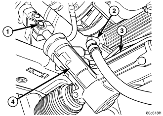
10. Remove the lower coupler pinch bolt (1) and slide the coupler off the gear (4).
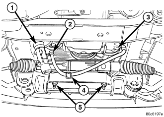
11. Remove the power steering lines (2) from the gear (1) .
12. Remove the mounting bolts (5) from the gear to the front cradle .
13. Remove the steering gear from the vehicle.
RHD - 4X2 & 4X4
1. Siphon the power steering fluid from the power steering reservoir.
NOTE: The steering column on vehicles with an automatic transmission may not be equipped with an internal locking shaft that allows the ignition key cylinder to be locked with the key. Alternative methods of locking the steering wheel for service will have to be used.
2. Lock the steering wheel to prevent spinning of the clockspring.
3. Raise and support the vehicle.
4. Remove the skid plate from under the front end to gain access to the gear (Refer to 13 - FRAME & BUMPERS/FRAME/FRONT SKID PLATE - REMOVAL).
5. Remove the tire and wheel assembly.
NOTE: Mark the alignment adjusting cams and tie rod end jam nuts on the steering gear for easier installation.
6. Remove the tie rod end nuts.
7. Separate tie rod ends from the knuckles with Puller C-3894-A.
8. Remove the lower intermediate shaft coupler pinch bolt (1) and slide the coupler off the gear (4).
9. Remove the power steering lines (2) from the gear (1) .
10. Remove the mounting bolts (5) from the gear (1) to the front cradle .
11. Remove the steering gear (1) from the vehicle.