INSTALLATION
BULB - A/C-HEAT CONTROL
WARNING: To avoid personal injury or death, on vehicles equipped with airbags, disable the supplemental restraint system before attempting any steering wheel, steering column, airbag, occupant classification system, seat belt tensioner, impact sensor, or instrument panel component diagnosis or service. Disconnect and isolate the battery negative (ground) cable, then wait two minutes for the system capacitor to discharge before performing further diagnosis or service. This is the only sure way to disable the supplemental restraint system. Failure to take the proper precautions could result in accidental airbag deployment.
CAUTION: Always use the correct bulb size and type for replacement. An incorrect bulb size or type may overheat and cause damage to the lamp, the socket or the lamp wiring.
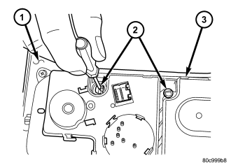
1. Align the bulb holder and bulb (2) with the keyed opening in the circuit board of the heater-A/C control (3).
2. Insert the bulb holder and bulb straight into the circuit board until the bulb holder is firmly seated.
3. Using a small thin-bladed screwdriver, rotate the bulb holder clockwise about 30 degrees on the circuit board to lock it into place.
4. Reinstall the center bezel (1) onto the instrument panel. (Refer to 23 - BODY/INSTRUMENT PANEL/INSTRUMENT PANEL CENTER BEZEL - INSTALLATION).
5. Reconnect the battery negative cable.
BULB - CMTC CONTROL
WARNING: To avoid personal injury or death, on vehicles equipped with airbags, disable the supplemental restraint system before attempting any steering wheel, steering column, airbag, occupant classification system, seat belt tensioner, impact sensor, or instrument panel component diagnosis or service. Disconnect and isolate the battery negative (ground) cable, then wait two minutes for the system capacitor to discharge before performing further diagnosis or service. This is the only sure way to disable the supplemental restraint system. Failure to take the proper precautions could result in accidental airbag deployment.
CAUTION: Always use the correct bulb size and type for replacement. An incorrect bulb size or type may overheat and cause damage to the lamp, the socket or the lamp wiring.
NOTE: The Compass Mini-Trip Computer (CMTC) in the overhead console includes either two or three incandescent illumination bulb and bulb holder units. Three bulbs are used only on vehicles that also feature the optional Universal Garage Door Opener (UGDO).
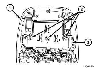
1. Align the bulb holder and bulb (2) with the keyed opening in the circuit board of the Compass Mini-Trip Computer (CMTC) (3).
2. Insert the bulb holder and bulb straight into the circuit board until the bulb holder is firmly seated.
3. Using a small thin-bladed screwdriver, rotate the bulb holder clockwise about 30 degrees on the circuit board to lock it into place.
4. Reinstall the overhead console (1) onto the headliner. (Refer to 8 - ELECTRICAL/OVERHEAD CONSOLE - INSTALLATION).
5. Reconnect the battery negative cable.
BULB - TRANSMISSION RANGE INDICATOR
WARNING: To avoid personal injury or death, on vehicles equipped with airbags, disable the supplemental restraint system before attempting any steering wheel, steering column, airbag, occupant classification system, seat belt tensioner, impact sensor, or instrument panel component diagnosis or service. Disconnect and isolate the battery negative (ground) cable, then wait two minutes for the system capacitor to discharge before performing further diagnosis or service. This is the only sure way to disable the supplemental restraint system. Failure to take the proper precautions could result in accidental airbag deployment.
CAUTION: Always use the correct bulb size and type for replacement. An incorrect bulb size or type may overheat and cause damage to the lamp, the socket or the lamp wiring.
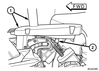
1. Align the base of the bulb with the transmission range indicator illumination lamp socket (2).
2. Push the bulb straight into the socket until the base is firmly seated.
3. Align the lamp socket and bulb with the keyed opening on the bottom of the indicator (1).
4. Insert the socket and bulb straight into the bottom of the indicator until the socket is firmly seated.
5. Rotate the socket clockwise about 30 degrees to lock it into place.
6. Reinstall the center console onto the floor panel transmission tunnel. (Refer to 23 - BODY/INTERIOR/FLOOR CONSOLE - INSTALLATION).
7. Reconnect the battery negative cable.