STANDARD PROCEDURE
- STANDARD PROCEDURE - MODULE LAMP REPLACEMENT
- STANDARD PROCEDURE - COURTESY LAMP REPLACEMENT
- STANDARD PROCEDURE - COMPASS CALIBRATION
- STANDARD PROCEDURE - COMPASS DEMAGNETIZING
- STANDARD PROCEDURE - COMPASS VARIATION ADJUSTMENT
- STANDARD PROCEDURE - ELECTRONIC VEHICLE INFORMATION CENTER PROGRAMMING
STANDARD PROCEDURE - MODULE LAMP REPLACEMENT
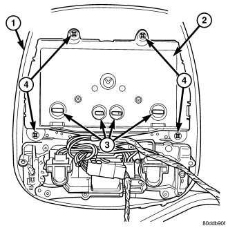
1. Remove the overhead console (1), (Refer to 8 - ELECTRICAL/OVERHEAD CONSOLE - REMOVAL).
2. Using a flat blade screwdriver twist out socket/lamp (3).
3. Replace lamp(s) as necessary.
STANDARD PROCEDURE - COURTESY LAMP REPLACEMENT
1. Open hood, disconnect and isolate the negative battery cable.
2. Remove the overhead console from the headliner.
3. Remove the lamp and socket assembly from the overhead console.
4. Remove the lamp bulb by pulling it straight out of its socket.
STANDARD PROCEDURE - COMPASS CALIBRATION
CAUTION: Do not place any external magnets, such as magnetic roof mount antennas, in the vicinity of the compass. Do not use magnetic tools when servicing the overhead console.
The electronic compass unit features a self-calibrating design, which simplifies the calibration procedure. This feature automatically updates the compass calibration while the vehicle is being driven. This allows the compass unit to compensate for small changes in the residual magnetism that the vehicle may acquire during normal use. If the compass readings appear to be erratic or out of calibration, perform the following calibration procedure. Also, new replacement Electronic Vehicle Information Center (EVIC) modules must have their compass calibrated using this procedure. Do not attempt to calibrate the compass near large metal objects such as other vehicles, large buildings, or bridges; or, near overhead or underground power lines.
Calibrate the compass manually as follows:
1. Turn the ignition switch to the On position. If the compass/thermometer data is not currently being displayed, momentarily depress and release the C/T push button to reach the compass/thermometer display.
2. Depress the Reset push button and hold the button down until “CAL” appears in the display. This takes about ten seconds, and appears about five seconds after “VARIANCE = XX” is displayed.
3. Release the Reset push button.
4. Drive the vehicle on a level surface, away from large metal objects and power lines, through three or more complete circles at between five and eight kilometers-per-hour (three and five miles-per-hour) in not less than 48 seconds. The “CAL” message will disappear from the display to indicate that the compass is now calibrated.
NOTE: If the “CAL” message remains in the display, either there is excessive magnetism near the compass, or the unit is faulty. Repeat the calibration procedure one more time.
NOTE: If the wrong direction is still indicated in the compass display, the area selected for calibration may be too close to a strong magnetic field. Repeat the calibration procedure in another location.
STANDARD PROCEDURE - COMPASS DEMAGNETIZING
A degaussing tool (Special Tool 6029) is used to demagnetize, or degauss, the overhead console forward mounting screw and the roof panel above the overhead console. Equivalent units must be rated as continuous duty for 110/115 volts and 60 Hz. They must also have a field strength of over 350 gauss at 7 millimeters (0.25 inch) beyond the tip of the probe.
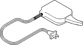
| Degaussing Tool 6029 |
To demagnetize the roof panel and the overhead console forward mounting screw, proceed as follows:
1. Be certain that the ignition switch is in the Off position, before you begin the demagnetizing procedure.
2. Connect the degaussing tool to an electrical outlet, while keeping the tool at least 61 centimeters (2 feet) away from the compass unit.
3. Slowly approach the head of the overhead console forward mounting screw with the degaussing tool connected.
4. Contact the head of the screw with the plastic coated tip of the degaussing tool for about two seconds.
5. With the degaussing tool still energized, slowly back it away from the screw. When the tip of the tool is at least 61 centimeters (2 feet) from the screw head, disconnect the tool.
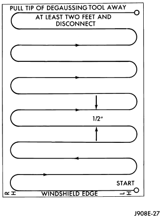
6. Place a piece of paper approximately 22 by 28 centimeters (8.5 by 11 inches), oriented on the vehicle lengthwise from front to rear, on the center line of the roof at the windshield header. The purpose of the paper is to protect the roof panel from scratches, and to define the area to be demagnetized.
7. Connect the degaussing tool to an electrical outlet, while keeping the tool at least 61 centimeters (2 feet) away from the compass unit.
8. Slowly approach the center line of the roof panel at the windshield header, with the degaussing tool connected.
9. Contact the roof panel with the plastic coated tip of the degaussing tool. Be sure that the template is in place to avoid scratching the roof panel. Using a slow, back-and-forth sweeping motion, and allowing 13 millimeters (0.50 inch) between passes, move the tool at least 11 centimeters (4 inches) to each side of the roof center line, and 28 centimeters (11 inches) back from the windshield header.
10. With the degaussing tool still energized, slowly back it away from the roof panel. When the tip of the tool is at least 61 centimeters (2 feet) from the roof panel, disconnect the tool.
11. Calibrate the compass, (Refer to 8 - ELECTRICAL/OVERHEAD CONSOLE - STANDARD PROCEDURE - COMPASS CALIBRATION). Adjust the compass variance, (Refer to 8 - ELECTRICAL/OVERHEAD CONSOLE - STANDARD PROCEDURE - COMPASS VARIATION ADJUSTMENT).
STANDARD PROCEDURE - COMPASS VARIATION ADJUSTMENT
Compass variance, also known as magnetic declination, is the difference in angle between magnetic north and true geographic north. In some geographic locations, the difference between magnetic and geographic north is great enough to cause the compass to give false readings. If this problem occurs, the compass variance setting may need to be changed.
To set the compass variance:
1. Using the Variance Settings map, find your geographic location and note the zone number.
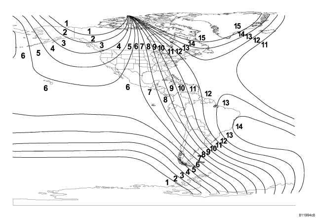
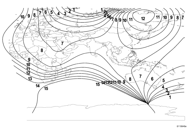
2. Turn the ignition switch to the On position. If the compass/thermometer data is not currently being displayed, momentarily depress and release the C/T push button to reach the compass/thermometer display.
3. Depress the Reset push button and hold the button down until “VARIANCE = XX” appears in the display. This takes about five seconds.
4. Release the Reset push button. “VARIANCE =XX ” will remain in the display. “XX” equals the current variance zone setting.
5. Momentarily depress and release the Step push button to step through the zone numbers, until the zone number for your geographic location appears in the display.
6. Momentarily depress and release the Reset push button to enter the displayed zone number into the Electronic Overhead Module memory.
7. Confirm that the correct directions are now indicated by the compass.
STANDARD PROCEDURE - ELECTRONIC VEHICLE INFORMATION CENTER PROGRAMMING
EVIC PROGRAMMING MODE
The Electronic Vehicle Information Center (EVIC) provides the vehicle operator with a user interface, which allows the selection of several optional customer programmable electronic features to suit individual preferences. The EVIC must be placed into its programming mode in order to view or change the programmable features. To enter the EVIC programming mode and to view or change the selected programmable features options, proceed as follows:
1. Turn the ignition switch to the On position.
2. Depress and release the Menu push button. The first item in the programmable features menu list will appear in the EVIC display.
3. Momentarily depress and release the Menu push button to step through the programmable features list. Each programmable feature and its currently selected option will appear on the EVIC display in the sequence shown in the Programmable Features list that follows.
4. Momentarily depress and release the Step push button to step through the available options for the programmable feature being displayed.
5. The option that last appears in the display with a programmable feature before exiting the programming mode, becomes the newly selected programmable feature option.
6. The EVIC exits the programming mode and returns to its normal operating mode when the C/T push button is depressed or when the end of the programmable features menu list is reached, whichever occurs first.
PROGRAMMABLE FEATURES
- LANGUAGE? - The options include English, Francais, Deutsch, Italiana, or Espanol. The default is English. All EVIC display nomenclature, including the trip computer functions, warning messages and the programmable features appear in the selected language.
- DISPLAY U.S. OR METRIC? - The options include U.S. and M. The default is U.S. This feature toggles the trip computer temperature, fuel economy and odometer display readings between U.S. and metric units of measure. It also changes the odometer display in the instrument cluster.
- AUTO DOOR LOCKS? - The options include Yes and No. The default is Yes. When Yes is selected, all doors lock automatically when vehicle speed reaches 25 km/h (15 mp/h). If YES is selected, a second programmable feature appears, AUTO UNLOCK ON EXIT? - The options again include Yes and No. The default is No. When Yes is selected, following each Auto Door Lock event all doors will automatically unlock when the driver door is opened, if the vehicle is stopped and the transmission gear selector is in Park or Neutral. The Auto Door Unlock event will only occur once following each Auto Door Lock event.
- REMOTE UNLOCK - The options include Driver Door 1st and All Doors. The default is Driver Door 1st. When Diver Door 1st is selected, only the driver door unlocks when the Unlock button of the Remote Keyless Entry (RKE) transmitter is depressed once. The Unlock button of the RKE transmitter must be depressed twice to unlock all doors. When All Doors is selected, all doors unlock when the Unlock button of the RKE transmitter is depressed once.
- SOUND HORN ON LOCK? - The options include Yes and No. The default is No. When Yes is selected, a short horn chirp will provide an audible confirmation when the RKE receiver recognizes a valid Lock signal from an RKE transmitter. When No is selected, no horn chirp will occur with the RKE Lock event. This feature may be selected independent of the FLASH LIGHTS WITH LOCKS? programmable feature.
- FLASH LIGHTS WITH LOCKS? - The options include Yes and No. The default is Yes. When Yes is selected, a single flash of the hazard warning lamps will provide an optical confirmation when the RKE receiver recognizes a valid Lock signal from an RKE transmitter, and two flashes of the same lamps will occur when the RKE receiver recognizes a valid Unlock signal from an RKE transmitter. When No is selected, no lamp flash will occur with the RKE Lock or Unlock event. This feature may be selected independent of the SOUND HORN ON LOCK? programmable feature.
- HEADLAMP DELAY = - The options include Off, 30 Sec, 60 Sec, and 90 Sec. The default is 90 Sec. When a time interval is selected, the headlamps will remain on for that length of time when the headlamps are turned off after the ignition is turned off, or if the Auto mode is selected on vehicles with the Auto Headlamps option. When Off is selected, the headlamp delay feature is disabled.
- SERVICE INTERVAL = - The options will vary depending on the market and engine: US/GAS engine - the options include from 2000 to 6000 miles in 500 mile increments (3200 to 9600 kilometers in 800 kilometer increments). The default is 6000 miles (9600 kilometers). The selected distance becomes the interval at which the Perform Service warning message will be displayed by the EVIC. EXPORT/GAS engine - the options include from 2000 to 7500 miles in 500 mile increments (3200 to 12000 kilometers in 800 kilometer increments). The default is 7500 miles (12000 kilometers). The selected distance becomes the interval at which the Perform Service warning message will be displayed by the EVIC. EXPORT/DIESEL engine - the options include 3125, 6250, 9375, 12500 miles ( 5, 10, 15, 20 kilometers). The default is 12500 miles (20 kilometers). The selected distance becomes the interval at which the Perform Service warning message will be displayed by the EVIC. If a new distance is selected, a second programmable feature appears, RESET SERVICE DISTANCE? - The options include No and Yes. The default is Yes. When Yes is selected, the accumulated distance since the last previous Perform Service warning message will be reset to zero because the service interval has been changed. When No is selected, the distance until the next Perform Service warning message is reduced by the accumulated distance since the last previous message.
- TRAIN REMOTE - When this feature is selected the driver can choose to train up to four remote keyless entry transmitters. The options include Yes and No. The default is No. When Yes is selected and the MENU button is pressed the EVIC will display “PRESS A VALID FOB KEY”. Follow the directions displayed in the EVIC, you have approximately 30 seconds to train each transmitter, after each transmitter is trained the EVIC will display “FOB #? TRAINED”.
- RETRAIN TIRE SENSORS - This programmable feature only applies to vehicles equipped with the optional Tire Pressure Monitoring System. The options include Yes and No. The default is No. When Yes is selected, and the MENU button is depressed, the EVIC will enter the training mode starting with the left front tire. Refer to the tires and wheels section for additional information.