CHECK VALVE
DESCRIPTION
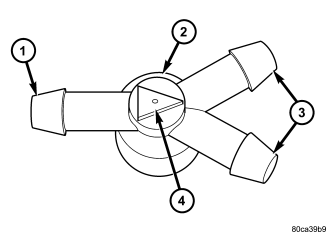
A single front washer system check valve (2) is standard equipment on this vehicle, and is installed in the front washer system plumbing. The front check valve is integral to the front washer nozzle plumbing wye fitting located in the cowl plenum area beneath the cowl plenum cover/grille panel near the base of the windshield. The check valve consists of a molded plastic body with a raised arrowhead (4) molded into its center section that indicates the direction of the flow through the valve, and three barbed hose nipples (1 and 3) formed in a wye configuration on the outside circumference of the center section of the valve body.
The front check valve cannot be adjusted or repaired and, if ineffective or damaged, it must be replaced.
OPERATION
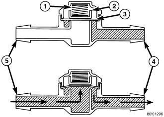
The front check valve provides more than one function in this application. It serves as a wye connector fitting between the cowl grille panel and washer nozzle sections of the front washer supply hose. It prevents washer fluid from draining out of the front washer supply hoses back to the washer reservoir. This drain-back would result in a lengthy delay when the front washer switch is actuated until washer fluid was dispensed through the front washer nozzles, because the washer pump would have to refill the front washer plumbing from the reservoir to the nozzles. Such a drain-back condition could also result in water, dirt, or other outside contaminants being siphoned into the washer system through the washer nozzle orifice. This water could subsequently freeze and plug the nozzle, while other contaminants could interfere with proper nozzle operation and cause improper nozzle spray patterns. In addition, the check valve prevents washer fluid from siphoning through the washer nozzles after the washer system is turned Off.
When the washer pump pressurizes and pumps washer fluid from the reservoir (5) through the washer plumbing, the fluid pressure unseats a diaphragm (3) from over a sump well within the valve by overriding the spring pressure (1) applied to it by a piston (2). With the diaphragm unseated, washer fluid is allowed to flow toward the two washer nozzles (4). When the washer pump stops operating, the spring pressure on the piston seats the diaphragm over the sump well in the valve and fluid flow in either direction within the washer plumbing is prevented.
REMOVAL
1. Unlatch and open the hood.
2. Remove both front wiper arms from the wiper pivots. (Refer to 8 - ELECTRICAL/WIPERS/WASHERS - FRONT/FRONT WIPER ARM - REMOVAL).
3. Remove the cowl plenum cover/grille panel from over the cowl plenum. (Refer to 23 - BODY/EXTERIOR/COWL GRILLE - REMOVAL).
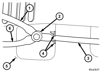
4. From the underside of the cowl plenum cover/grille panel (5), disconnect the cowl plenum (3) and washer nozzle hoses (1 and 6) from the three barbed nipples of the front check valve (2).
5. Remove the front check valve from the underside of the cowl plenum cover/grille panel.
INSTALLATION
1. Position the front check valve (2) to the underside of the cowl plenum cover/grille panel (5). Be certain that the flow direction arrow molded into the front check valve body is oriented towards the front washer nozzles.
2. From the underside of the cowl plenum cover/grille panel, reconnect the cowl plenum (3) and washer nozzle hoses (1 and 6) to the three barbed nipples of the front check valve.
3. Reinstall the cowl plenum cover/grille panel over the cowl plenum. (Refer to 23 - BODY/EXTERIOR/COWL GRILLE - INSTALLATION).
4. Reinstall both front wiper arms onto the wiper pivots. (Refer to 8 - ELECTRICAL/FRONT WIPERS/WASHERS/FRONT WIPER ARM - INSTALLATION).
5. Close and latch the hood.