AUTOMATIC TRANSMISSION - 42RLE
- DESCRIPTION
- OPERATION
- STANDARD PROCEDURE - ALUMINUM THREAD REPAIR
- REMOVAL
- DISASSEMBLY
- ASSEMBLY
- INSTALLATION
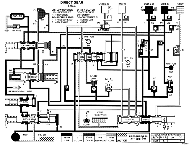
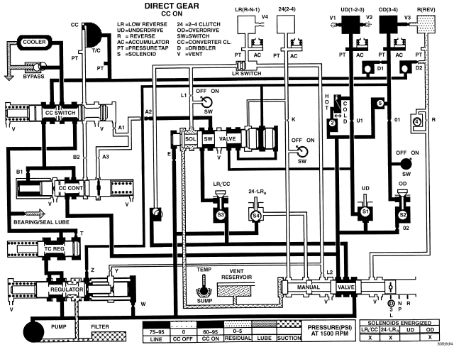
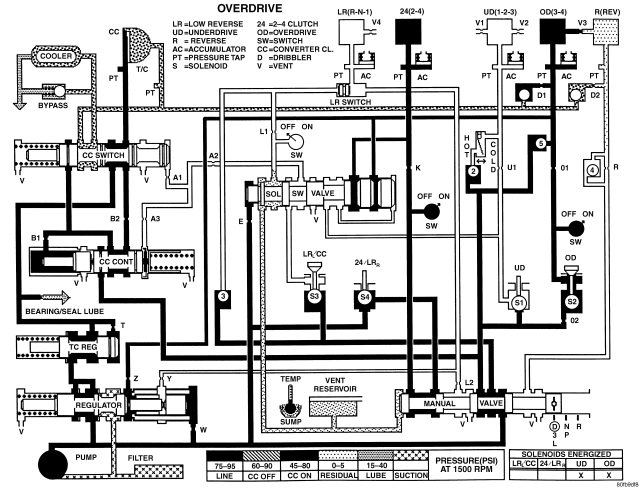
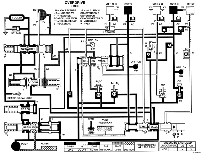
- SCHEMATICS AND DIAGRAMS - 42RLE TRANSMISSION
DESCRIPTION
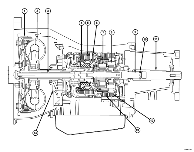
The 42RLE is a four-speed transmission that is a conventional hydraulic/mechanical assembly controlled with adaptive electronic controls and monitors. The hydraulic system of the transmission consists of the transmission fluid, fluid passages, hydraulic valves, and various line pressure control components. An input clutch assembly which houses the underdrive, overdrive, and reverse clutches is used. It also utilizes separate holding clutches: 2nd/4th gear and Low/Reverse. The primary mechanical components of the transmission consist of the following:
- Three multiple disc input clutches
- Two multiple disc holding clutches
- Four hydraulic accumulators
- Two planetary gear sets
- Hydraulic oil pump
- Valve body
- Solenoid/Pressure switch assembly
Control of the transmission is accomplished by fully adaptive electronics. Optimum shift scheduling is accomplished through continuous real-time sensor feedback information provided to the Transmission Control Module (TCM) portion of the Powertrain Control Module (PCM).
The TCM is the heart of the electronic control system and relies on information from various direct and indirect inputs (sensors, switches, etc.) to determine driver demand and vehicle operating conditions. With this information, the TCM can calculate and perform timely and quality shifts through various output or control devices (solenoid pack, transmission control relay, etc.).
The TCM also performs certain self-diagnostic functions and provides comprehensive information (sensor data, DTC's, etc.) which is helpful in proper diagnosis and repair. This information can be viewed with the DRB® scan tool.
TRANSMISSION IDENTIFICATION
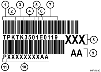
The 42RLE transmission can be identified by a barcode label that is affixed to the upper left area of the bellhousing.
The label contains a series of digits that can be translated into useful information such as transmission part number (10), date of manufacture (4, 5), manufacturing origin (2), assembly line identifier (6), build sequence number (7), etc..
If the tag is not legible or is missing, the “PK” number, which is stamped into the left rear flange of the transmission case, can be referred to for identification. The entire part number, build code, and sequence number are stamped into the flange.
OPERATION
The 42RLE transmission ratios are:| First | 2.84 : 1 |
| Second | 1.57 : 1 |
| Third | 1.00 : 1 |
| Overdrive | 0.69 : 1 |
| Reverse | 2.21 : 1 |
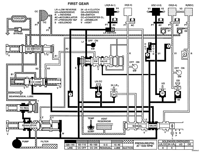
FIRST GEAR POWERFLOW
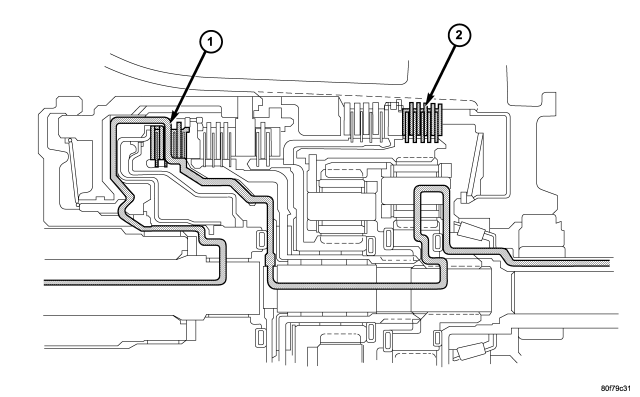
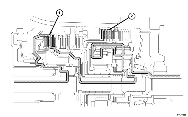
In first gear range, torque input is through the underdrive clutch (1) to the underdrive hub assembly. The underdrive hub is splined to the rear sun gear. When the underdrive clutch is applied, it rotates the underdrive hub and rear sun gear. The L/R clutch (2) is applied to hold the front carrier/rear annulus assembly. The rear sun gear drives the rear planetary pinion gears. The rear planetary pinion gears are forced to walk around the inside of the stationary rear annulus gear. The pinions are pinned to the rear carrier and cause the rear carrier assembly to rotate as they walk around the annulus gear. This provides the torque output for first gear. The other planetary gearset components are freewheeling. The first gear ratio is 2.84:1.
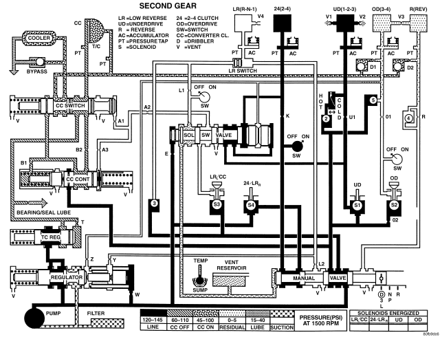
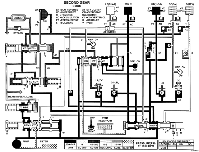
SECOND GEAR POWERFLOW
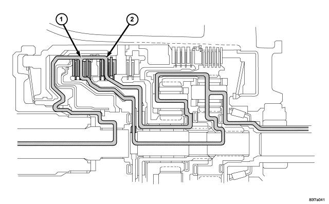
Second gear is achieved by having both planetary gear sets contribute to torque multiplication. As in first gear, torque input is through the underdrive clutch (1) to the rear sun gear. The 2/4 clutch (2) is applied to hold the front sun gear stationary. The rotating rear sun gear turns the rear planetary pinions. The rear pinions rotate the rear annulus/front carrier assembly. The pinions of the front carrier walk around the stationary front sun gear. This transmits torque to the front annulus/rear carrier assembly, which provides output torque and a gear ratio of 1.57:1.
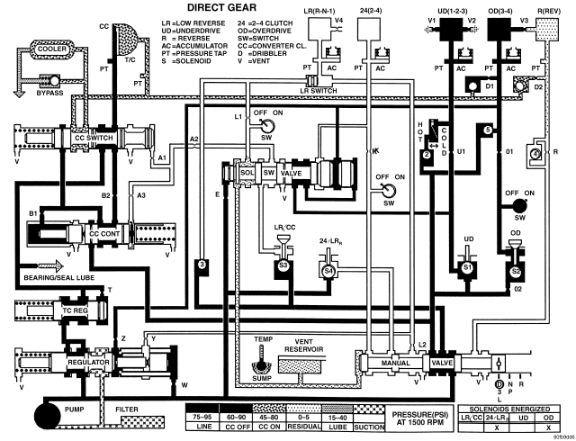
THIRD GEAR POWERFLOW
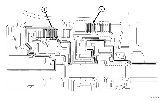
In third gear, two input clutches are applied to provide torque input: the underdrive clutch (1) and overdrive clutch (2). The underdrive clutch rotates the rear sun gear, while the overdrive clutch rotates the front carrier/rear annulus assembly. The result is two components (rear sun gear and rear annulus gear) rotating at the same speed and in the same direction. This effectively locks the entire planetary gearset together and is rotated as one unit. The gear ratio in third is 1:1.
FOURTH GEAR POWERFLOW
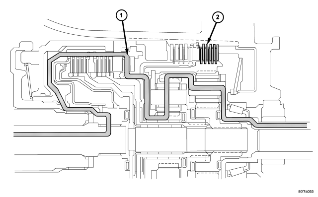
In fourth gear input torque is through the overdrive clutch (1) which drives the front carrier. The 2/4 clutch (2) is applied to hold the front sun gear. As the overdrive clutch rotates the front carrier, it causes the pinions of the front carrier to walk around the stationary front sun gear. This causes the front carrier pinions to turn the front annulus/rear carrier assembly which provides output torque. In fourth gear, transmission output speed is more than engine input speed. This situation is called overdrive and the gear ratio is 0.69:1.
REVERSE GEAR POWERFLOW
In reverse, input power is through the reverse clutch (1). When applied, the reverse clutch drives the front sun gear through the overdrive hub and shaft. The L/R clutch (2) is applied to hold the front carrier/rear annulus assembly stationary. The front carrier is being held by the L/R clutch so the pinions are forced to rotate the front annulus/rear carrier assembly in the reverse direction. Output torque is provided, in reverse, with a gear ratio of 2.21:1.
STANDARD PROCEDURE - ALUMINUM THREAD REPAIR
Damaged or worn threads in the aluminum transmission case and valve body can be repaired by the use of Heli-Coils®, or equivalent. This repair consists of drilling out the worn-out damaged threads. Then tap the hole with a special Heli-Coil® tap, or equivalent, and installing a Heli-Coil® insert, or equivalent, into the hole. This brings the hole back to its original thread size.
Heli-Coil®, or equivalent, tools, and inserts are readily available from most automotive parts suppliers.
REMOVAL
1. Disconnect battery negative cable.
2. Raise and support vehicle.
3. Disconnect and lower or remove necessary exhaust components.
4. Remove engine-to-transmission bending braces or engine collar.
5. Remove starter motor. (Refer to 8 - ELECTRICAL/STARTING/STARTER MOTOR - REMOVAL)
6. If transmission is being removed for overhaul, remove transmission oil pan, drain fluid and reinstall pan. (Refer to 21 - TRANSMISSION/AUTOMATIC - 42RLE/FLUID - STANDARD PROCEDURE)
7. Remove torque converter access structural collar.
8. Rotate crankshaft in clockwise direction until converter bolts are accessible. Then remove bolts one at a time. Rotate crankshaft with socket wrench on dampener bolt.
9. Mark propeller shaft and axle yokes for assembly alignment. Then disconnect and remove propeller shafts. (Refer to 3 - DIFFERENTIAL & DRIVELINE/PROPELLER SHAFT/PROPELLER SHAFT - REMOVAL)
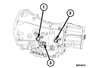
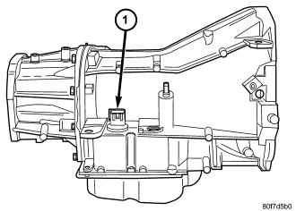
10. Disconnect wires from the input and output speed sensors .
11. Disconnect wires from the transmission range sensor and the solenoid/pressure switch assembly .
12. Disconnect gearshift cable from transmission manual valve lever.
13. Disconnect shift cable and electrical connector from transfer case.
14. Support rear of engine with safety stand or jack.
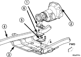
15. Raise transmission slightly with service jack to relieve load on skid plate and transmission support.
16. Remove bolts securing rear support and cushion to transmission and skid plate.
17. Remove bolts attaching skid plate to frame and remove skid plate. (Refer to 13 - FRAME & BUMPERS/FRAME/TRANSFER CASE SKID PLATE - REMOVAL)
18. Disconnect transfer case vent hose.
19. Remove transfer case. (Refer to 21 - TRANSMISSION/TRANSFER CASE - REMOVAL)
20. Remove fill tube bracket bolts and pull tube and vent hose out of transmission. Retain fill tube seal. Remove the bolt attaching transfer case vent tube to converter housing.
21. Remove the fuel line bracket bolt.
22. Disconnect fluid cooler lines at transmission.
23. Remove crank shaft position sensor.
24. Remove all converter housing bolts.
25. Carefully work transmission and torque converter assembly rearward off engine block dowels.
26. Hold torque converter in place during transmission removal.
27. Lower transmission and remove assembly from under the vehicle.
28. To remove torque converter, carefully slide torque converter out of the transmission.
DISASSEMBLY
NOTE: If the transmission is being reconditioned (clutch/seal replacement) or replaced, it is necessary to perform the Quick Learn Procedure using the DRBIII® Scan Tool (Refer to 8 - ELECTRICAL/ELECTRONIC CONTROL MODULES/TRANSMISSION CONTROL MODULE - STANDARD PROCEDURE).
Before disassembling transmission, move the shift lever clockwise as far as it will go and then remove the shift lever.
NOTE: Tag all clutch pack assemblies, as they are removed, for reassembly identification.
CAUTION: Do not intermix clutch discs or plates as the unit might then fail.
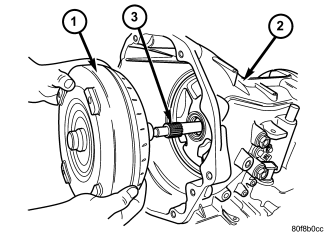
1. Remove the torque converter from the transmission input shaft .
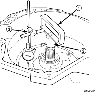
2. Measure input shaft end play using End Play Set 8266. Set up the required pieces from End Play Set 8266 and a dial indicator as . Move input shaft in and out to obtain end play reading. End play specifications are 0.127 to 0.635 mm (0.005 to 0.025 inch). Record indicator reading for reference when reassembling the transmission. If endplay exceeds the specified range, the #4 thrust plate needs to be inspected and changed if necessary.
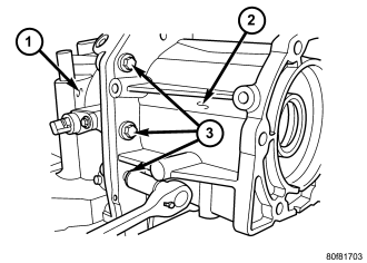
NOTE: The four bolts along the bottom of the adapter housing have a sealing patch applied from the factory. Note the locations of these bolts and separate these bolts for reuse.
3. Remove the bolts that hold the adapter housing onto the transmission case.
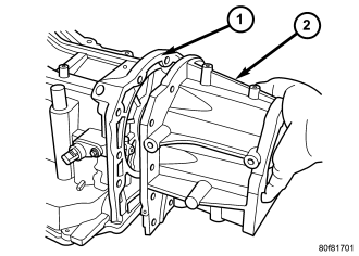
NOTE: There are two pry slots located near the bottom corners of the housing for separating the housing from the transmission case
4. Remove the adapter housing from the transmission case.
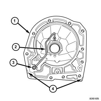
5. Inspect the lube tube grommet for damage. If the grommet lip is damaged, it will need to be replaced.
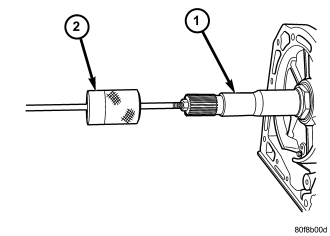
6. Using a Slide Hammer C-3752 , remove the 4X4 stub shaft from the transmission output shaft. Inspect the cir-clip on the shaft for damage and replace the clip if necessary.
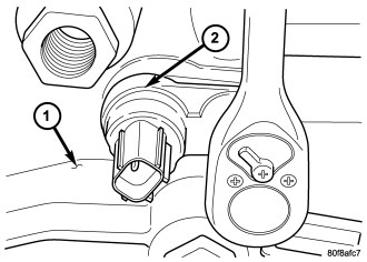
7. Remove the input speed sensor bolt and sensor.
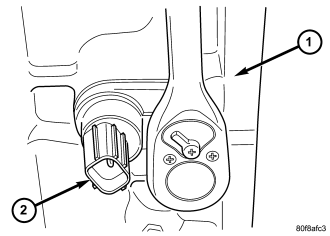
8. Remove the output speed sensor bolt and sensor .
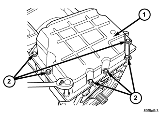
NOTE: One of the oil pan bolts has a sealing patch applied from the factory. Separate this bolt for reuse.
9. Remove the transmission oil pan bolts .
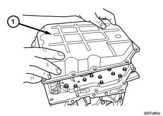
10. Remove the transmission oil pan .
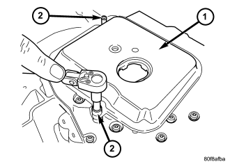
11. Remove the transmission oil filter screws .
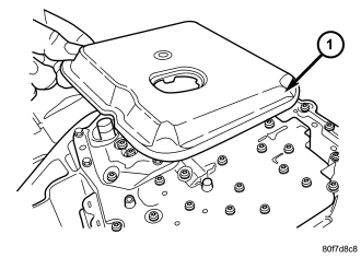
12. Remove transmission oil filter.
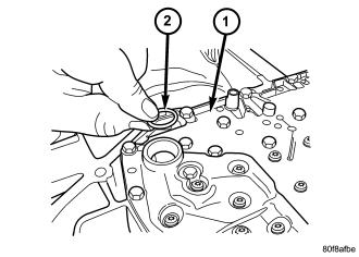
13. Remove the oil filter o-ring from the valve body .
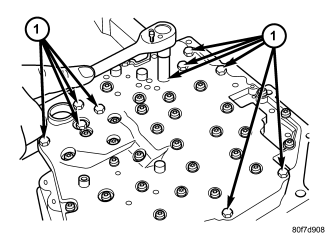
14. Remove valve body-to-case bolts .
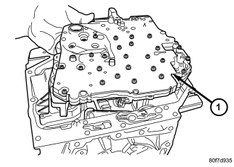
CAUTION: Do not handle the valve body by the manual shaft. Damage could result.
15. Remove valve body from transmission .
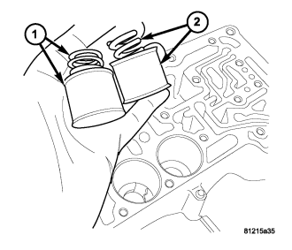
16. Remove underdrive and overdrive accumulators .
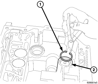
17. Remove the low/reverse accumulator snap ring .
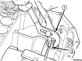
18. Remove the low/reverse accumulator plug .
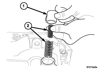
19. Remove low/reverse accumulator piston and springs .
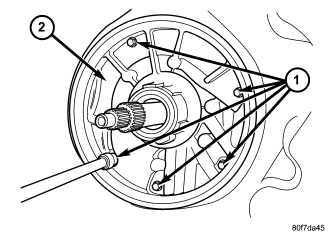
NOTE: The oil pump bolts are not to be reused.
20. Remove and discard the oil pump-to-case bolts .
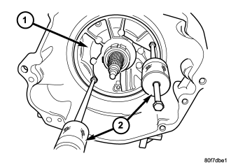
21. Remove oil pump using Slide Hammers C-3752 .
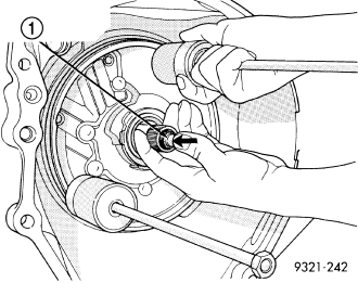
22. Remove oil pump while pushing in on input shaft .
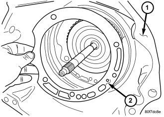
23. Remove oil pump gasket .
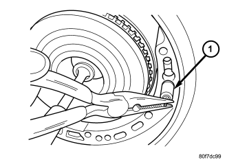
CAUTION: By-pass valve must be replaced if transmission failure occurs.
24. Remove the cooler by-pass valve .
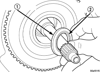
25. Remove the #1 caged needle bearing .
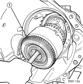
26. Remove the input clutch assembly .
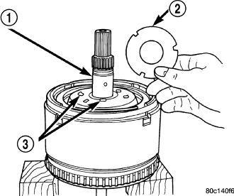
27. Remove the #4 thrust plate .
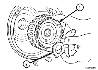
28. Remove the front sun gear assembly and #4 thrust washer (if still in place) .
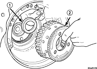
29. Remove the front carrier/rear annulus and #6 needle bearing .
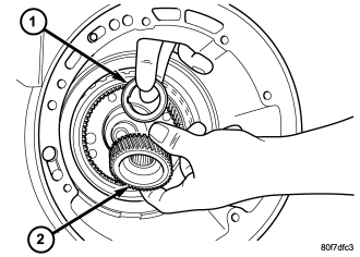
NOTE: The number seven needle bearing has three antireversal tabs and is common with the number five and number two position. The orientation should allow the bearing to seat flat against the rear sun gear .
30. Remove the rear sun gear and #7 needle bearing and .
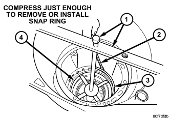
NOTE: Verify that Compressor 5058A is centered properly over the 2/4 clutch retainer before compressing. If necessary, fasten the Compressor 5058A bar to the bellhousing flange with any combination of locking pliers and bolts to center the tool properly.
31. Install and load Compressor 5058A to remove the 2/4 clutch retainer snap ring .
NOTE: The 2/4 Clutch Piston has bonded seals which are not individually serviceable. Seal replacement requires replacement of the piston assembly.
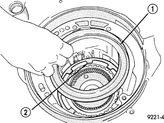
32. Remove the 2/4 clutch retainer .
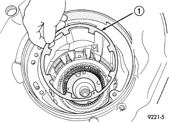
33. Remove the 2/4 clutch return spring .
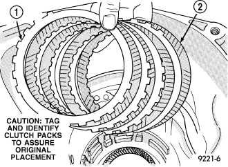
34. Remove the 2/4 clutch pack.
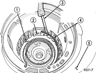
35. Remove the tapered snap ring .
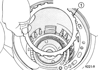
36. Remove the low/reverse reaction plate .
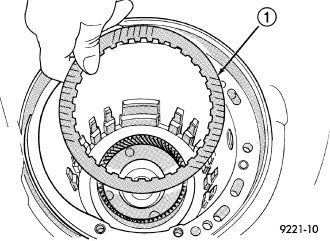
37. Remove one (1) low/reverse clutch disc to facilitate snap ring removal .
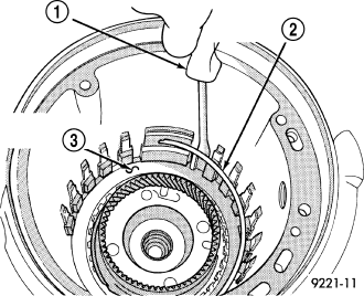
38. Remove the low/reverse reaction plate snap ring .
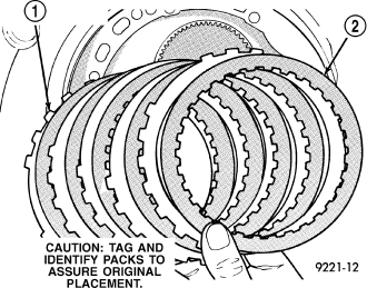
39. Remove the low/reverse clutch pack .
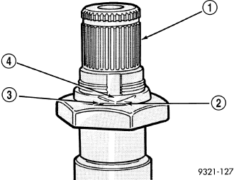
CAUTION: Failure to grind and open stakes of the output shaft nut will result in thread damage to the shaft during nut removal.
WARNING: Wear safety goggles while grinding stake nuts.
40. Using a die grinder or equivalent, grind the stakes in the shoulder of the shaft nuts as shown in . Do not grind all the way through the nut and into the shaft. There are two stakes on each nut.
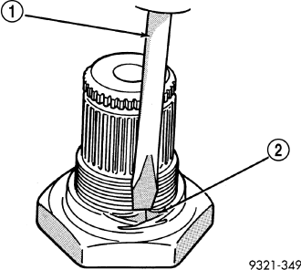
41. Using a small chisel, carefully open the stakes on nut .
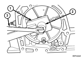
42. Use Wrench 6497 and Wrench 6498A to remove the transfer shaft nut or the output shaft nut .
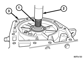
43. Remove the output shaft from case using a press .
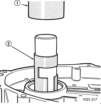
Use Remover 6596 with a press to remove the front output shaft bearing cup .
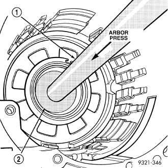
44. Use Remover 6597 and Universal Handle C-4171 and Handle Extension C-4171-2 to press the rear output shaft bearing cup rearward .
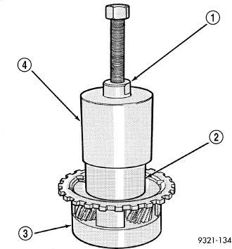
45. Remove the rear carrier front bearing cone .
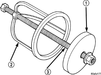
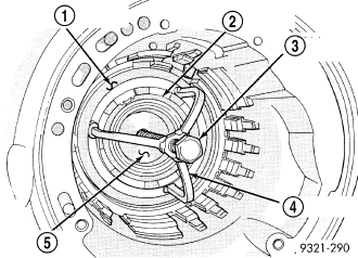
46. Install and load compressor
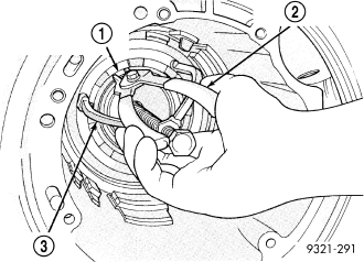
47. Remove the low/reverse belleville spring snap ring .
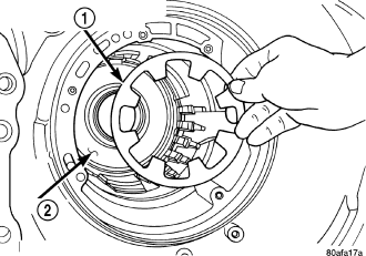
48. Remove the low/reverse piston belleville spring .
49. Remove the park sprag pivot retaining screw.
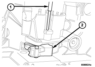
50. Drive out the anchor shaft using suitable punch .
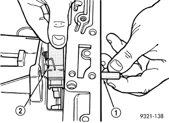
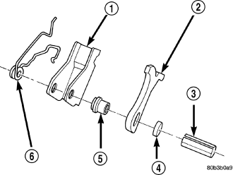
51. Remove the guide bracket pivot shaft . Inspect all components for wear and replace if necessary.
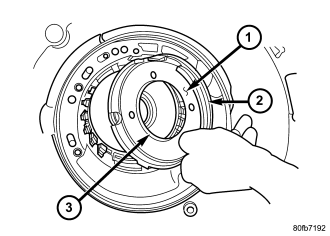
NOTE: The Low/Reverse Clutch Piston has bonded seals which are not individually serviceable. Seal replacement requires replacement of the piston assembly.
52. Remove the low/reverse clutch piston .
53. Remove the low/reverse piston retainer screws.
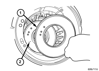
54. Remove low/reverse piston retainer .
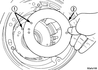
55. Remove the low/reverse piston retainer gasket .
ASSEMBLY
NOTE: If the transmission assembly is being reconditioned (clutch/seal replacement) or replaced, it is necessary to perform the Quick Learn Procedure using the DRBIII® Scan Tool (Refer to 8 - ELECTRICAL/ELECTRONIC CONTROL MODULES/TRANSMISSION CONTROL MODULE - STANDARD PROCEDURE).
1. Install the output bearing cups using Installer 5050A.
2. Install low/reverse piston retainer gasket .
3. Install low/reverse piston retainer .
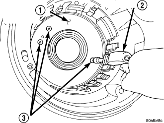
4. Install low/reverse piston retainer-to-case screws and torque to 5 N·m (45 in. lbs.).
NOTE: The Low/Reverse Clutch Piston has bonded seals which are not individually serviceable. Seal replacement requires replacement of the piston assembly.
5. Install low/reverse clutch piston .
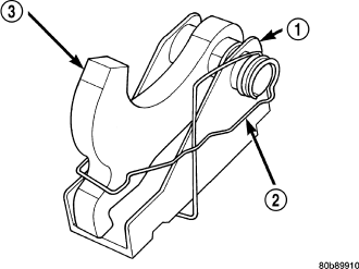
6. Assemble guide bracket assembly as shown in .
CAUTION: When installing, be sure guide bracket and split sleeve touch the rear of the transmission case.
7. Install guide bracket pivot shaft .
8. Install park sprag pivot retaining screw and torque to 4.5 N·m (40 in. lbs.).
9. Install low/reverse piston belleville spring into position .
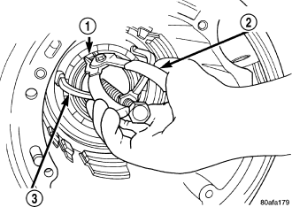
10. Install snap ring and remove compressor tool .
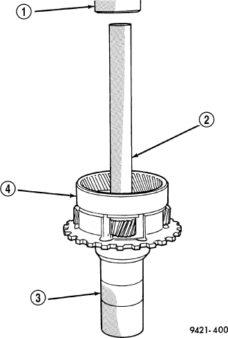
11. Install rear carrier front bearing cone .
12. Check output bearing preload. Output bearing preload must be checked and adjusted if any of the following items have been replaced:
- Output shaft (rear carrier assembly)
- Output shaft bearings
- Transmission case
a. PRELOAD CHECK/SHIM SELECTION: Install rear output shaft bearing cone and Support Plate 6618 A.
b. Install Support Plate 6618 A . Lightly tighten retaining screws. Screws should be below the plate surface, but do not snug screws.
c. Turn case over on arbor press so that the plate is resting on the press base. CAUTION: The output shaft will extend through the hole of Support Plate 6618 A. Ensure your press table has clearance for the output shaft.
d. Install shim on output shaft . Apply small amount of petrolatum onto the shim to hold it in place. Use the original shim as a starting point. If original shim is not available, use the thickest shim available.
e. Install output shaft/rear carrier into rear bearing. The shaft must be pressed into position. Use special tool Bearing Installer MD-998911 (Disc) Extension handle C- 4171 and C4171-2 (Handle) to press shaft into rear bearing .
f. Do not re-use old output shaft nut because the removed stake weakens the nut flange. Using special Wrench 6497 and Wrench socket 6498-A, install new output shaft nut. Do not reuse old output shaft nut. Tighten new output shaft nut to 271 N·m (200 ft. lbs.).
g. Check the turning torque of the output shaft . The shaft should have 1 to 8 in. lbs. of turning torque. If the turning torque is higher than 8 in. lbs., install a thicker shim. If turning torque is less than 1 in. lb., install a thinner shim. Make sure there is no end play.
h. The new nut must be staked after the correct turning torque is obtained . Use special Staking Tool 6639 to stake output shaft nut. CAUTION: Failure to stake nut could allow the nut to back-off during use.
13. Install low/reverse clutch pack . Leave uppermost disc out to facilitate snap ring installation.
14. Install low/reverse reaction plate snap ring .
15. Install one low/reverse clutch disc .
16. Install low/reverse reaction plate with flat side up .
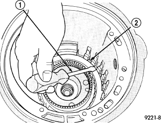
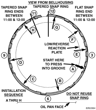
17. Install a new tapered snap ring (tapered side out) . Make sure that the snap ring ends are oriented as shown.
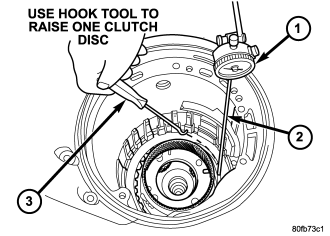
18. Measure low/reverse clutch pack. . Press down clutch pack with finger and zero dial indicator. Record measurement in four (4) places and take average reading. Low/Reverse clutch pack clearance is 0.84 to 1.60 mm (0.033 to 0.063 inch).
19. Select the proper low/reverse reaction plate to achieve specifications.
NOTE: The 2/4 Clutch Piston has bonded seals which are not individually serviceable. Seal replacement requires replacement of the piston assembly.
20. Install 2/4 clutch pack .
21. Install 2/4 clutch belleville spring .
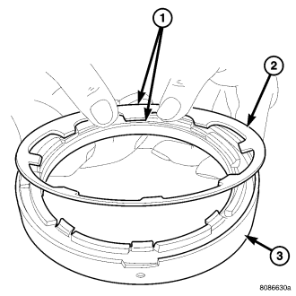
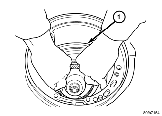
22. Install 2/4 clutch retainer .
NOTE: Verify that Compressor 5058A is centered properly over the 2/4 clutch retainer before compressing. If necessary, fasten the 5058A bar to the bellhousing flange with any combination of locking pliers and bolts to center the tool properly.
23. Compress 2/4 clutch just enough to facilitate snap ring installation.
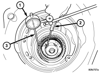
24. Measure 2/4 clutch clearance: Set up dial indicator as shown in . Press down clutch pack with finger and zero dial indicator. Record measurement in four (4) places and take average reading. The 2/4 clutch pack clearance is 0.76 to 2.64 mm (0.030 to 0.104 inch). If not within specifications, the clutch is not assembled properly or is excessively worn. There is no adjustment for the 2/4 clutch clearance.
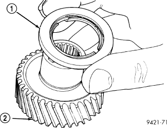
25. Install the #7 needle bearing to the rear sun gear . The number 7 needle bearing has three antireversal tabs and is common with the number 5 and number 2 position. The orientation should allow the bearing to seat flat against the rear sun gear. A small amount of petrolatum can be used to hold the bearing to the rear sun gear.
26. Install rear sun gear and #7 needle bearing .
27. Install front carrier/rear annulus assembly and #6 needle bearing .
28. Install front sun gear assembly and #4 thrust washer .
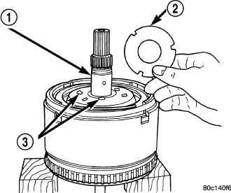
29. Determine proper #4 thrust plate thickness.
a. Select the thinnest #4 thrust plate thickness.
b. Install #4 thrust plate using petrolatum to hold into position.
c. Install input clutch assembly. Ensure the input clutch assembly is completely seated by viewing position through input speed sensor hole. If the speed sensor tone wheel is not centered in the opening, the input clutch assembly is not seated properly.
d. Remove the oil pump o-ring and install oil pump and gasket to transmission. Tighten the oil pump bolts to 30 N·m (265 in. lbs.). Use screw-in dowels or phillips-head screwdrivers to align pump to case. Be sure to reinstall O-ring on oil pump after selecting the proper No. 4 thrust plate.
e. Measure the input shaft end play with the transmission in the vertical position. This will ensure that the measurement will be accurate.
f. Set up and measure endplay using End Play Set 8266 and Dial Indicator Set C3339.
g. Measure input shaft end play. Input shaft end play must be 0.127 to 0.635 mm (0.005 to 0.025 inch). For example, if end play reading is 0.055 inch, select No. 4 Thrust Plate which is 0.071 to 0.074 thick. This should provide an input shaft end play reading of 0.020 inch, which is within specifications.
h. Remove oil pump, gasket, and input clutch assembly to gain access to and install proper #4 thrust plate.
30. Install #1 caged needle bearing .
31. Install input clutch assembly with proper thrust plate .
CAUTION: By-pass valve MUST be replaced if transmission failure occurs.
32. Replace cooler by-pass valve if transmission failure has occurred .
NOTE: To align oil pump, gasket, and case during installation, use threaded dowels or phillips screwdrivers.
33. Install oil pump gasket .
NOTE: Do not reuse original oil pump bolts.
34. Install oil pump and torque the new oil pump-to-case bolts to 30 N·m (265 in. lbs.) .
35. Install low/reverse accumulator.
36. Install low/reverse accumulator plug .
37. Install low/reverse accumulator snap ring .
38. Install underdrive and overdrive accumulators and springs .
CAUTION: Do not handle the valve body by the manual shaft. Damage could result.
39. Install valve body into place .
40. Install seven (7) valve body-to-case bolts and torque to 12 N·m (105 in. lbs.).
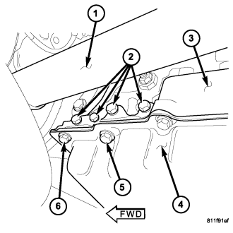
NOTE: Before installing the oil pan bolt in the bolt hole located between the torque converter clutch on and U/D clutch pressure tap circuits , it will be necessary to replentish the sealing patch on the bolt using Mopar® Lock & Seal Adhesive.
41. Install transmission oil filter . Tighten the bolts to 5 N·m (45 in. lbs.)
42. Install transmission oil pan with a bead of Mopar® ATF RTV. Torque oil pan-to-case bolts to 20 N·m (14.5 ft. lbs.).
NOTE: Before installing either speed sensor bolt,it will be necessary to replenish the sealing patch on the bolt using Mopar® Lock & Seal Adhesive.
43. Install both speed sensors into transmission case . Torque the speed sensor bolts to 9 N·m (80 in. lbs.).
44. As a final check of the transmission, measure the input shaft end play. This will indicate when a #4 thrust plate change is required. The #4 thrust plate is located behind the overdrive clutch hub. Attach a dial indicator to transmission bell housing with its plunger seated against end of input shaft . Move input shaft in and out to obtain end play reading. Input shaft end play must be 0.127 to 0.635 mm (0.005 to 0.025 inch). If not within specifications, make the necessary thrust plate adjustment.
45. Inspect the lube tube grommet for damage. If the grommet lip is damaged, it will need to be replaced.
46. Install the 4X4 stub shaft onto the transmission output shaft.
47. Place a bead of Mopar® ATF RTV on the rear surface of the transmission case for the adapter housing.
48. Install the adapter housing onto the transmission case.
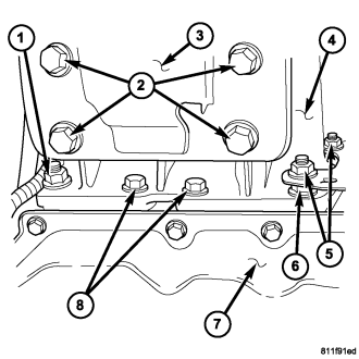
NOTE: Before installing the lowermost four adapter housing bolts,it will be necessary to replenish the sealing patch on the bolts using Mopar® Lock & Seal Adhesive.
49. Install the bolts that hold the adapter housing onto the transmission case. Be sure to install any stud bolts to their original locations. Tighten the bolts to 54 N·m (40 ft.lbs.).
INSTALLATION
1. Check torque converter hub and hub drive notches for sharp edges burrs, scratches, or nicks. Polish the hub and notches with 320/400 grit paper and crocus cloth if necessary. The hub must be smooth to avoid damaging pump seal at installation.
2. Lubricate converter drive hub and oil pump seal lip with transmission fluid.
3. Align converter and oil pump.
4. Carefully insert converter in oil pump. Then rotate converter back and forth until fully seated in pump gears.
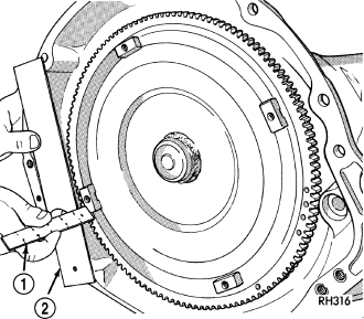
5. Check converter seating with steel scale and straightedge . Surface of converter lugs should be 1/2 in. to rear of straightedge when converter is fully seated.
6. Temporarily secure converter with C-clamp.
7. Lightly grease crankshaft flange hole.
8. Position transmission on jack and secure it with safety chains.
9. Check condition of converter driveplate. Replace the plate if cracked, distorted or damaged. Also be sure transmission dowel pins are seated in engine block and protrude far enough to hold transmission in alignment.
10. Raise transmission and align converter with drive plate and converter housing with engine block.
11. Move transmission forward. Then raise, lower or tilt transmission to align converter housing with engine block dowels.
12. Carefully work transmission forward and over engine block dowels until converter hub is seated in crankshaft.
13. Install bolts that attach transmission converter housing to engine block. Tighten bolts to 129 N·m (95 ft. lbs)
CAUTION: Be sure the converter housing is fully seated on the engine block dowels before tightening any bolts.
14. Install torque converter attaching bolts. Tighten bolts to 88 N·m (65 ft. lbs.).
15. Install transmission fill tube , new seal and breather hose
16. Install fuel line bracket bolt.
17. Install crank shaft position sensor.
18. Connect transmission cooler lines to transmission.
19. Install transfer case onto transmission. (Refer to 21 - TRANSMISSION/TRANSFER CASE - INSTALLATION)
20. Remove engine support fixture.
21. Remove transmission jack.
22. Connect input and output speed sensor wires .
23. Connect wires to the transmission range sensor and the solenoid/pressure switch assembly .
24. Install converter housing support collar.
25. Install exhaust pipes and support brackets, if removed.
26. Install starter motor (Refer to 8 - ELECTRICAL/STARTING/STARTER MOTOR - INSTALLATION) and cooler line bracket. \
27. Connect transfer case shift cable and electrical connectors.
28. Adjust gearshift linkage, if necessary.
29. Align and connect propeller shaft(s). (Refer to 3 - DIFFERENTIAL & DRIVELINE/PROPELLER SHAFT/PROPELLER SHAFT - INSTALLATION)
30. Install transmission structural collar.
31. Fill transfer case to bottom edge of fill plug hole.
32. Install all skid plates and attach skid plate to transmission rear support. (Refer to 13 - FRAME & BUMPERS/FRAME/TRANSFER CASE SKID PLATE - INSTALLATION)
33. Lower vehicle and connect battery negative cable.
34. Fill transmission to correct level with Mopar® ATF +4.
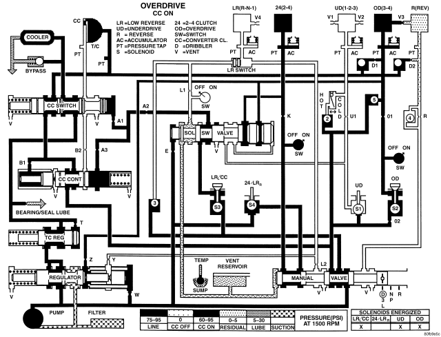
SCHEMATICS AND DIAGRAMS - 42RLE TRANSMISSION