VALVE BODY
DESCRIPTION
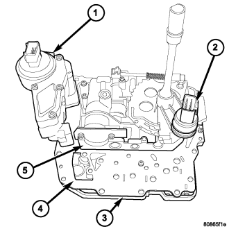
The valve body assembly consists of a cast aluminum valve body (5),separator plate (4), and transfer plate (3). The valve body contains valves and check balls that control fluid delivery to the torque converter clutch, solenoid/pressure switch assembly, and frictional clutches.
Also mounted to the valve body assembly are the solenoid/pressure switch assembly and the transmission range sensor (2).
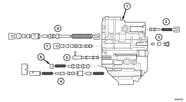
The valves contained within the valve body (1) include the following :
- Regulator valve(2)
- Solenoid switch valve(7)
- Manual valve(5)
- Converter clutch switch valve(6)
- Converter clutch control valve(4)
- Torque converter regulator valve(2)
- Low/Reverse switch valve(3)
In addition, the valve body also contains the thermal valve, #2, 3, 4 & 5 check balls and the 2/4 accumulator assembly.
OPERATION
NOTE: (Refer to 21 - TRANSMISSION/AUTOMATIC - 42RLE - SCHEMATICS AND DIAGRAMS) for a visual aid in determining valve location, operation and design.
THERMAL VALVE
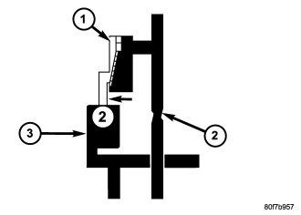
The thermal valve (1) is a bi-metallic shudder valve that helps control the venting rate of oil pressure in the underdrive clutch passage during release of the clutch. When the oil temperature is approximately 20 degrees F. ( - 6 degrees C.) or less, the valve is fully open to assist in venting oil past the U1 orifice (2). At temperatures above 20 degrees F . ( - 6 degrees C.) , the valve starts to close and becomes fully closed at approximately 140 degrees. The thermal valve is located in the transfer plate of the valve body.
REGULATOR VALVE
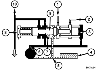
The regulator valve (9) controls hydraulic pressure in the transmission. It receives unregulated pressure from the pump (6), which works against spring tension (8) to maintain oil at specific pressures. A system of sleeves and ports allows the regulator valve to work at one of three predetermined pressure levels. Regulated oil pressure is also referred to as “line pressure.”
SOLENOID SWITCH VALVE
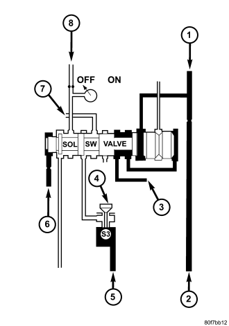
The solenoid switch valve controls line pressure from the LR/CC solenoid (4). In one position, it allows the low/reverse clutch to be pressurized. In the other, it directs line pressure to the converter control and converter clutch valves (7).
MANUAL VALVE
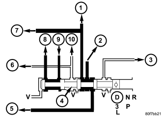
The manual valve (4) is operated by the mechanical shift linkage. Its primary responsibility is to send line pressure to the appropriate hydraulic circuits and solenoids. The valve has three operating ranges or positions.
CONVERTER CLUTCH SWITCH VALVE
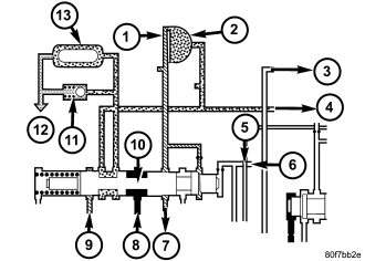
The main responsibility of the converter clutch switch valve (10) is to control hydraulic pressure applied to the front (off) side of the converter clutch piston. Line pressure from the regulator valve (5) is fed to the torque converter regulator valve (8). The pressure is then directed to the converter clutch switch valve (10) and to the front side of the converter clutch piston. This pressure pushes the piston back and disengages the converter clutch.
CONVERTER CLUTCH CONTROL VALVE
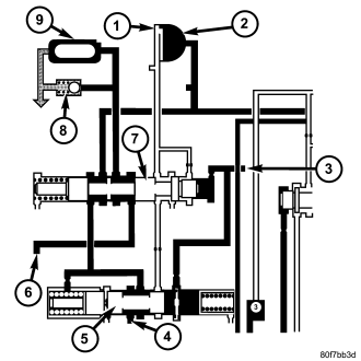
The converter clutch control valve (5) controls the back (on) side of the torque converter clutch (1). When the controller energizes or modulates the LR/CC solenoid to apply the converter clutch piston, both the converter clutch control valve (5) and the converter control valve move, allowing pressure to be applied to the back side of the clutch.
T/C REGULATOR VALVE
The torque converter regulator valve slightly regulates the flow of fluid to the torque converter.
LOW/REVERSE SWITCH VALVE
The low/reverse clutch is applied from different sources, depending on whether low (1st) gear or reverse is selected. The low/reverse switch valve alternates positions depending on from which direction fluid pressure is applied. By design, when the valve is shifted by fluid pressure from one channel, the opposing channel is blocked. The switch valve alienates the possibility of a sticking ball check, thus providing consistent application of the low/reverse clutch under these operating conditions.
REMOVAL
NOTE: If valve body is being reconditioned or replaced, it is necessary to perform the Quick Learn Procedure. (Refer to 8 - ELECTRICAL/ELECTRONIC CONTROL MODULES/TRANSMISSION CONTROL MODULE - STANDARD PROCEDURE)
1. Disconnect the TRS and solenoid wiring connectors.
2. Disconnect the shift cable from the shift lever (at the transmission).
3. Move the manual shift lever clockwise as far as it will go. This should be one position past the L position. Then remove the manual shift lever.
NOTE: One of the oil pan bolts has a sealing patch applied from the factory. Separate this bolts for reuse.
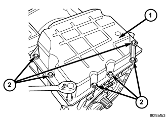
4. Remove transmission pan bolts (2).
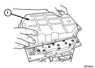
5. Remove transmission oil pan (1).
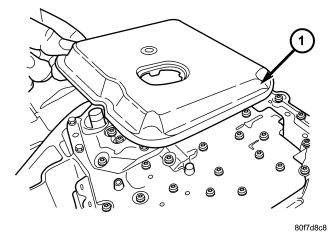
6. Remove oil filter (1) from valve body. It is held in place by two screws.
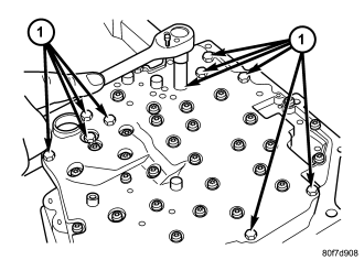
7. Remove valve body bolts-to-case (1).
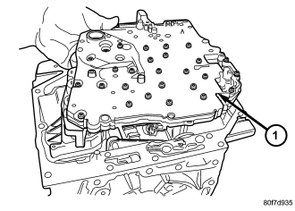
CAUTION: The overdrive and underdrive accumulators and springs may fall out when removing the valve body.
8. Carefully remove valve body assembly (1) from the transmission.
DISASSEMBLY
NOTE: If the valve body is being reconditioned or replaced, it is necessary to perform the Quick Learn Procedure using the DRBIII® Scan Tool (Refer to 8 - ELECTRICAL/ELECTRONIC CONTROL MODULES/TRANSMISSION CONTROL MODULE - STANDARD PROCEDURE)
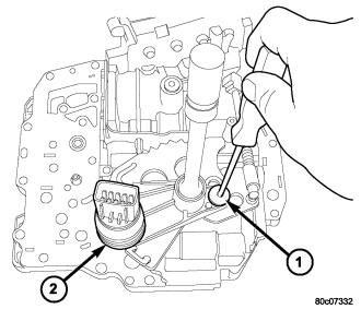
1. Remove manual shaft seal.
2. Remove manual shaft screw (1).
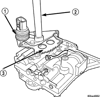
3. Remove Transmission Range Sensor (TRS) (1) and manual shaft (2).
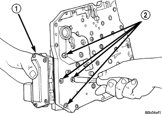
4. Remove Solenoid/Pressure Switch Assembly (1) from valve body.
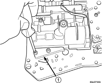
5. Remove valve body stiffener plate (1).
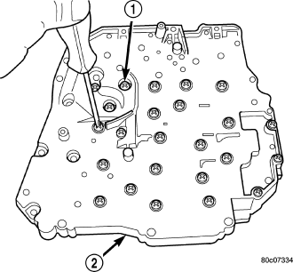
6. Invert valve body assembly and remove transfer plate-to-valve body screws (1).
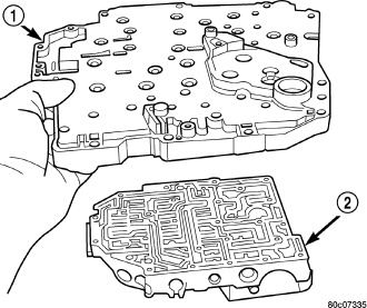
7. Remove transfer/separator plate (1) from valve body (2)
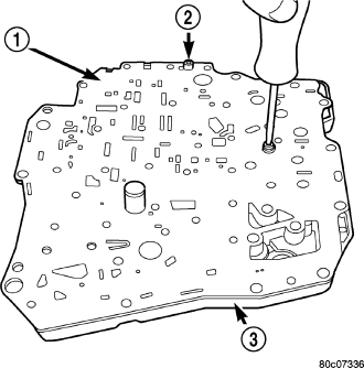
8. Remove separator plate-to-transfer plate screws (2).
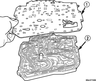
9. Remove separator plate (1) from transfer plate (2).
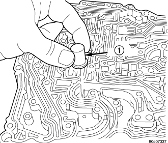
10. Remove the oil screen (1) from the transfer plate.
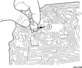
11. Remove thermal valve (1) from transfer plate.
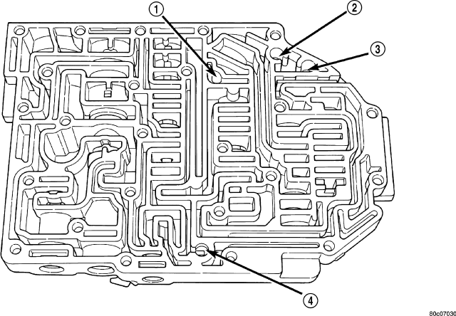
12. Remove valve body check balls (1-4). Note their location for assembly ease .
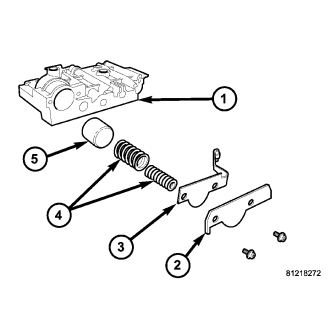
13. Remove 2/4 accumulator assembly (1-5).
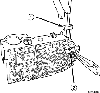
14. Remove dual retainer plate (2) from valve body. Use special Remover / Installer tool 6301 (1) to remove plate (2).
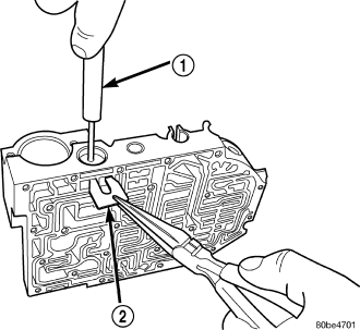
15. Remove regulator valve spring retainer (2).
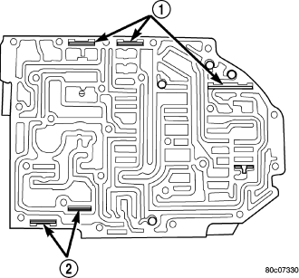
16. Remove remaining retainers (1, 2).
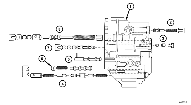
17. Remove all valves and springs.
18. Cleanliness through entire disassembly and assembly of the valve body cannot be overemphasized. When disassembling, each part should be washed in a suitable solvent, then dried by compressed air. Do not wipe parts with shop towels. All mating surfaces in the valve body are accurately machined; therefore, careful handling of all parts must be exercised to avoid nicks or burrs.
ASSEMBLY
NOTE: If the valve body assembly is being reconditioned or replaced, it is necessary to perform the Quick Learn Procedure using the DRBIII® Scan Tool. (Refer to 8 - ELECTRICAL/ELECTRONIC CONTROL MODULES/TRANSMISSION CONTROL MODULE - STANDARD PROCEDURE)
1. Install all valves and springs as shown.
2. Install regulator valve spring retainer (2).
3. Install dual retainer plate (2) using Tool 6301 (1).
4. Verify that all retainers (1, 2) are installed as shown. Retainers should be flush or below valve body surface.
5. Install 2/4 Accumulator components (1-5) as shown. Torque 2/4 Accumulator retainer plate to 5 N·m (45 in. lbs.).
6. Install check balls into position as shown. If necessary, secure them with petrolatum or transmission assembly gel for assembly ease.
7. Install thermal valve (1) to the transfer plate.
8. Install the oil screen (1) to the transfer plate.
9. Install separator plate (1) to transfer plate (2).
10. Install the two separator plate-to-transfer plate screws (2).
11. Install the transfer plate (1) to the valve body (2).
12. Install the transfer plate-to-valve body screws (1) and torque to 5 N·m (45 in. lbs.).
13. Install the stiffener plate (1).
14. Install the solenoid/pressure switch assembly (1) and screws to the transfer plate and torque to 5.5 N·m (50 in. lbs.).
15. Install the manual shaft/rooster comb (3) and transmission range sensor (1) to the valve body.
16. Install the TRS/manual shaft retaining screw (1) and torque to 5 N·m (45 in. lbs.).
17. Install manual shaft seal.
INSTALLATION
1. Install valve body into position and start bolts (1). Torque valve body to transmission case bolts (1) to 12 N·m (105 in. lbs.) torque.
2. Install transmission oil filter (1).
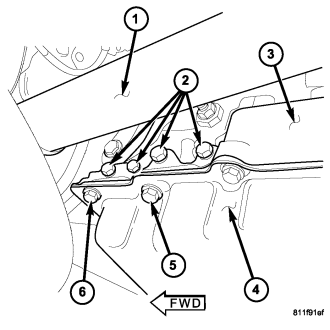
NOTE: Before installing the oil pan bolt in the bolt hole (5) located between the torque converter clutch on and U/D clutch pressure tap circuits , it will be necessary to replentish the sealing patch on the bolt using Mopar® Lock & Seal Adhesive.
3. Make sure oil pan (1) and case rail are clean and dry. Install an 1/8” bead of RTV to the transmission oil pan and install to case. Tighten bolts (2) to 20 N·m (14.5 ft. lbs.).
4. Lower vehicle and connect the TRS connector.
5. Connect solenoid/pressure switch assembly connector.
6. Lower vehicle.
7. Fill transmission with ATF+4, Automatic Transmission Fluid. Verify proper fluid level. (Refer to 21 - TRANSMISSION/AUTOMATIC - 42RLE/FLUID - STANDARD PROCEDURE)
NOTE: If the valve body has been reconditioned or replaced, it is necessary to perform the Quick Learn Procedure. (Refer to 8 - ELECTRICAL/ELECTRONIC CONTROL MODULES/TRANSMISSION CONTROL MODULE - STANDARD PROCEDURE)