CLUTCH-A/C COMPRESSOR
DESCRIPTION
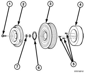
The A/C compressor clutch assembly consists of a stationary electromagnetic field coil (4), bearing and pulley assembly (3), shims (7) and a clutch plate (2) that is splined to the compressor shaft and secured by a bolt (1). These components provide the means to engage and disengage the A/C compressor from the engine accessory drive belt.
The A/C clutch field coil is retained to the front of the compressor with three screws (5) and the A/C clutch bearing and pulley assembly is retained by a snap ring (6).
OPERATION
The A/C compressor clutch components provide the means to engage and disengage the A/C compressor from the engine accessory drive belt. When the electromagnetic A/C clutch field coil is energized, it magnetically draws the clutch plate into contact with the clutch pulley and drives the compressor shaft. When the coil is not energized, the pulley freewheels on the clutch hub bearing, which is part of the pulley assembly.
A/C compressor clutch engagement is controlled by the powertrain control module (PCM) in the engine compartment.
The A/C compressor clutch components cannot be repaired and must be replaced if found inoperative or damaged.
REMOVAL
NOTE: The compressor clutch assembly can be serviced with the refrigerant system fully-charged.
NOTE: Typical A/C compressor and clutch assembly shown in illustrations.
1. Disconnect and isolate the negative battery cable.
2. On 2.8L equipped models, remove the air cleaner housing (refer to 9 - ENGINE/AIR INTAKE SYSTEM/HOUSING-AIR CLEANER - REMOVAL).
3. On 3.8L equipped models, remove the coolant recovery container (refer to 7 - COOLING/ENGINE/COOLANT RECOVERY CONTAINER - REMOVAL).
4. Remove the accessory drive belt (refer to 7 - COOLING/ACCESSORY DRIVE/BELTS-DRIVE - REMOVAL).
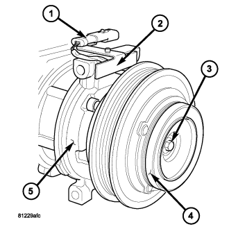
5. Disconnect the engine wire harness from the compressor clutch field coil connector (1) located on the top of the A/C compressor (5).
6. Remove the screw that secures the connector bracket (2) to the A/C compressor and position the bracket and wire lead out of the way.
NOTE: A band-type oil filter wrench or a strap wrench may be used to hold the clutch plate from turning during compressor shaft bolt removal.
7. Hold the clutch plate (4) from turning and remove the compressor shaft bolt (3).
CAUTION: Do not pry between the clutch plate and the pulley and bearing assembly to remove the clutch plate from the compressor shaft as this may damage the clutch plate.
NOTE: Use care not to lose any clutch shim(s) during removal of the clutch plate, as they may be reused during the clutch plate installation process.
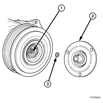
8. Tap the clutch plate (2) lightly with a plastic mallet to release it from the splines on the compressor shaft (1) and remove the clutch plate and shim(s) (3).
NOTE: The pulley and bearing assembly can be removed from the compressor by hand or, if required, with a two jaw puller.
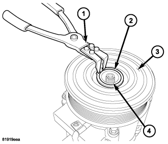
9. Using Snap Ring Pliers 9764 or equivalent (1), remove the snap ring (2) that secures the pulley and bearing assembly (3) to the front of the A/C compressor (4).
10. Remove the pulley and bearing assembly from the front of the A/C compressor. If required, install a two jaw puller and turn the puller center-bolt clockwise until the pulley and bearing assembly is completely removed.
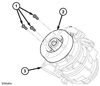
11. Remove the three screws (1) that secure the compressor clutch field coil (2) to the front of the A/C compressor (3) and remove the field coil.
INSTALLATION
NOTE: Typical A/C compressor and clutch assembly shown in illustrations.
1. Align the dowel pin on the back of the compressor clutch field coil (2) with the hole in the front of the A/C compressor (3) and position the field coil onto the compressor. Be certain that the compressor clutch field coil wire lead is properly routed so that it is not pinched between the A/C compressor and the field coil.
CAUTION: The field coil retaining screws must be securely installed or they may vibrate out, resulting in a clutch failure and severe damage to the A/C compressor.
2. Install the three screws (1) that secure the compressor clutch field coil to the front of the A/C compressor. Tighten the screws to 5 N·m (44 in. lbs.)..
CAUTION: Be certain to position the compressor clutch field coil wire lead so that it is not damaged during A/C compressor pulley and bearing installation.
CAUTION: When installing the pulley and bearing assembly, DO NOT mar the friction surfaces of the pulley or premature failure of the clutch will result.
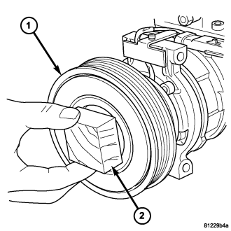
3. Install the pulley and bearing assembly (1) onto the front of the A/C compressor. If necessary, tap the pulley gently with a block of wood (2) placed on the pulley friction surface.
CAUTION: The snap ring must be fully and properly seated in the groove or it will vibrate out, resulting in a clutch failure and severe damage to the A/C compressor.
NOTE: A new snap ring must be used to secure the pulley and bearing assembly to the A/C compressor. The bevel side of the snap ring must face outward.
4. Using Snap Ring Pliers 9764 or equivalent (1), install the snap ring (2) that secures the pulley and bearing assembly (3) to the front of the A/C compressor (4). Be certain that the snap ring is fully and properly seated in the groove.
5. If the original clutch plate (2) and pulley and bearing assembly are to be reused, reinstall the original shim(s) (3) onto the compressor shaft (1). If a new clutch plate and pulley and bearing assembly are being used, install a trial stack of shims 1.50 mm (0.059 in.) thick onto the compressor shaft.
6. Install the clutch plate (4) onto the front of the A/C compressor (5).
7. Install the compressor shaft bolt (3). Tighten the bolt to 20 N·m (177 in. lbs.).
NOTE: The shims may compress after tightening the shaft bolt. Check the air gap in four or more places to verify the air gap is correct. Spin the pulley before performing a final check of the air gap.
NOTE: On models with the clutch plate recessed into the pulley, use a 90° wire gap gauge to measure the clutch air gap. On other models, use a blade type feeler gauge to measure the air gap.
8. With the clutch plate assembled tight against the shim(s), measure the air gap between the clutch plate and the pulley and bearing assembly. The air gap should be between 0.30 - 0.60 mm (0.012 - 0.024 in.). If the air gap is not between specifications, add or subtract shims as needed until the correct air gap is obtained.
CAUTION: Be certain that the compressor clutch field coil wire harness is properly routed so that it is not pinched between the A/C compressor and the field coil connector bracket.
9. Carefully route the compressor clutch field coil wire lead and install the connector bracket (2) and retaining screw onto the A/C compressor. Tighten the screw to 4.3 N·m (38 in. lbs.)..
10. Connect the engine wire harness to the compressor clutch field coil connector.
11. Install the accessory drive belt (refer to 7 - COOLING/ACCESSORY DRIVE/BELTS-DRIVE - INSTALLATION).
12. On 2.8L equipped models, install the air cleaner housing (refer to 9 - ENGINE/AIR INTAKE SYSTEM/HOUSING-AIR CLEANER - INSTALLATION).
13. On 3.8L equipped models, install the coolant recovery container (refer to 7 - COOLING/ENGINE/COOLANT RECOVERY CONTAINER - INSTALLATION).
14. Reconnect the negative battery cable.