CARRIER PLATE
DESCRIPTION
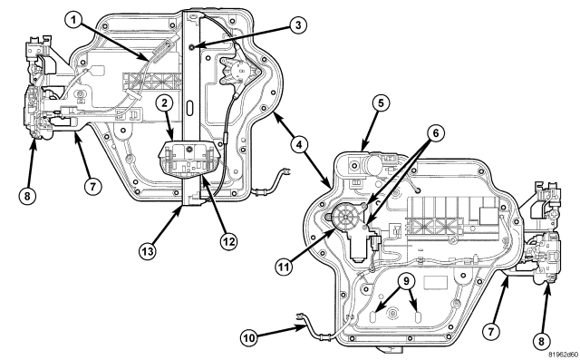
| POWER CARRIER PLATE |
| 1 - LATCH & LOCK CABLES |
| 2 - GLASS CLIP |
| 3 - REGULATOR SCREWS |
| 4 - CARRIER PLATE |
| 5 - INSIDE HANDLE |
| 6 - REGULATOR MOTOR SCREWS |
| 7 - LATCH MOUNTING BRACKET |
| 8 - LATCH |
| 9 - GLASS DISCONNECT HOLES (PLUGS MUST BE REMOVED TO SERVICE GLASS) |
| 10 - WIRE HARNESS |
| 11 - MOTOR |
| 12 - GLASS LIFT PLATE |
| 13 - REGULATOR |
NOTE: Full front door shown, full rear door similar.
Door carrier plates include the hardware, window regulators, latch, remote handle and links and wiring harness. In addition to providing manufacturing efficiencies, the door modules benefit the customer too. Having all the parts assembled into a module improves build accuracy and fit and finish between the components and trim as a result of greater communication between the release engineers and suppliers.
CAUTION: Care must be used when servicing the carrier plate that the seal isn't damaged.
REMOVAL
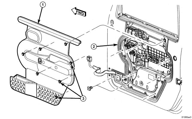
NOTE: Front door trim shown, rear door similar.
1. Position the glass into the down position.
2. Remove the trim panel (1), (Refer to 23 - BODY/DOORS - REAR/TRIM PANEL - REMOVAL).
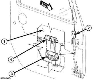
3. If equipped, using a punch or similar tool, carefully remove the glass disconnect hole plugs, (Refer to 23 - BODY/DOOR - FRONT/CARRIER PLATE - DESCRIPTION).
4. Release the two glass retainer tabs (3) and separate the glass clip (4) from the regulator lift plate and position into the full up position.
5. Position the glass (1) into the full up position and using tape or equivalent, secure the glass.
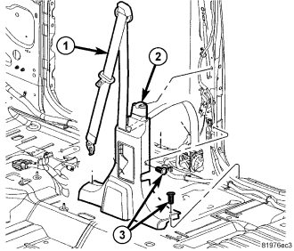
6. Remove the lower B-pillar trim panel (2), (Refer to 23 - BODY/INTERIOR/B-PILLAR TRIM - REMOVAL).
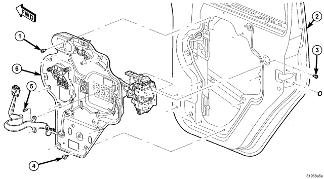
7. Disconnect the door wire harness at the B-pillar and separate the check strap from the hook.
8. Remove the screws (5) and separate the wire harness push pins from the door structure.
9. Remove the door handle screw (1).
10. Remove the latch screws (3).
11. Separate the foam seal and disconnect the exterior handle rods from the access hole in the carrier plate.
12. Remove the carrier plate screws (4) and remove the carrier plate assembly (6) from the door.
INSTALLATION
1. Place the latch assembly into the door opening and install the carrier plate (6) onto the door.
2. Install the latch screws (3) and tighten to 8 N·m (71 in. lbs.) top screws first.
3. Install the eight carrier plate screws (4) and tighten to 10 N·m (90 in. lbs.).
4. Install the inside door handle screw (1) and tighten to 8.5 N·m (75 in. lbs.).
5. Connect the exterior handle latch rods.
6. Replace the foam sealer over the access hole.
7. Install the wire harness onto the door and install the screws (5).
8. Connect the wire harness electrical connector at the B-pillar.
NOTE: Front door shown, rear door similar.
9. Slowly lower the glass (1) all the way down into the regulator lift plate (3) and seat the glass clip (4) fully until a snap sound is heard.
10. Seal the glass disconnect holes with a suitable foam tape or equivalent.
NOTE: Front door shown, rear door similar.
11. Install the door trim panel (1), (Refer to 23 - BODY/DOORS - REAR/TRIM PANEL - INSTALLATION).
12. Install the lower B-pillar trim (2), (Refer to 23 - BODY/INTERIOR/B-PILLAR TRIM - INSTALLATION).