COVER-CYLINDER HEAD
DESCRIPTION
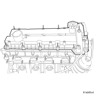
The cylinder head cover and the intake manifold on this engine are made of cast aluminum. The cylinder head cover also incorporates a oil drain back hole for the crankcase ventilation (CCV) system.
REMOVAL
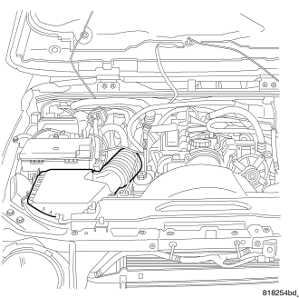
1. Disconnect the battery. (Refer to 8 - ELECTRICAL/BATTERY SYSTEM/CABLES - REMOVAL)
2. Remove the air cleaner housing.
3. Remove the upper air deflector.
4. Remove the fan.
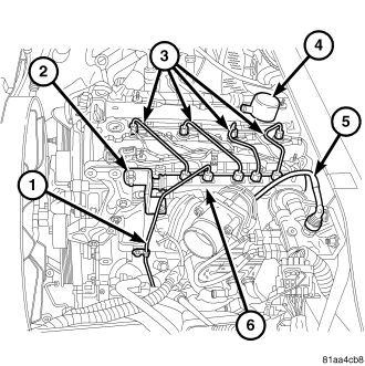
5. Remove the fuel lines.
6. Remove the high pressure fuel feed line.
7. Disconnect the fuel rail pressure sensor.
8. Disconnect the fuel pressure solenoid.
9. Remove the fuel rail.
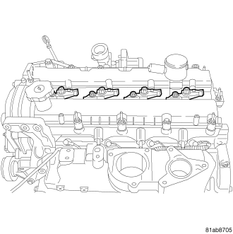
10. Disconnect the fuel injector connectors.
11. Remove the fuel injectors.
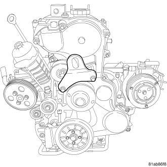
12. Remove the front lifting bracket.
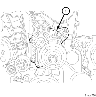
13. Remove the idler pulley.
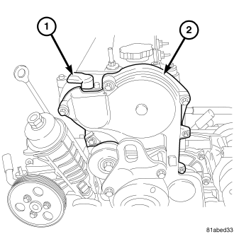
14. Disconnect the CMP sensor (1).
15. Remove the CMP sensor (1).
16. Remove the upper front cover.
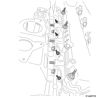
17. Disconnect and position aside the glow plug harness.
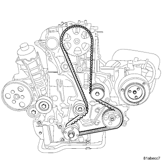
18. Remove the timing belt.
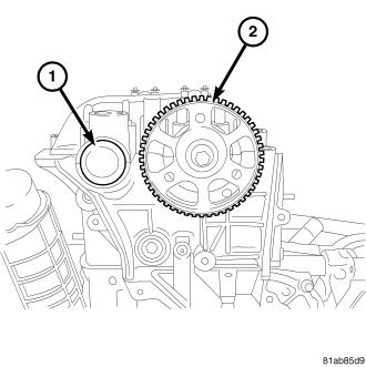
19. Remove the exhaust camshaft oil seal (1).
20. Remove the camshaft sprocket (2).
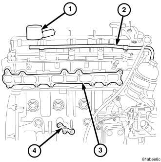
21. Disconnect the oil separator (1).
22. Remove the vacuum line (2) from the cylinder head cover.
23. Remove the cylinder head cover.
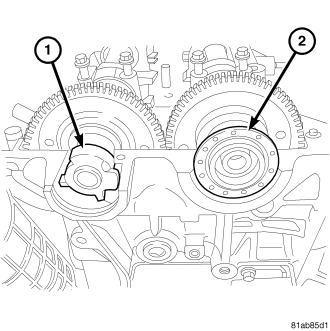
24. Remove the intake camshaft oil seal (2).
INSTALLATION
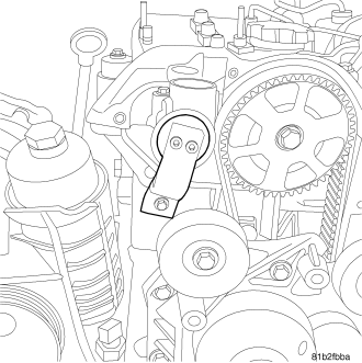
1. Install the camshaft locking tool.
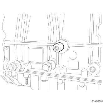
2. Make sure the crankshaft locking tool is installed.
3. Install the intake camshaft oil seal (2).
4. Install the cylinder head cover.
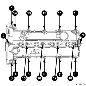
5. Using the above sequence, torque the bolts to 11 Nm (97 lbs. in.).
6. Install the fuel injectors. (Refer to 14 - FUEL SYSTEM/FUEL INJECTION/FUEL INJECTOR - INSTALLATION)
7. Install the glow plugs. Torque the glow plugs to 14 Nm (124 lbs. in.).
8. Position and connect and the glow plug harness.
9. Install the intake manifold. (Refer to 9 - ENGINE/MANIFOLDS/INTAKE MANIFOLD - INSTALLATION)
10. Connect the oil separator (1).
11. Install the vacuum line (2).
12. Install the exhaust camshaft oil seal (1).
13. Install the camshaft sprocket (2). Torque the bolt to 64 Nm (47 lbs. ft.).
14. Install the timing belt.
15. Adjust the timing belt tensioner (turn it clockwise) by lining up the center notch with the aluminum cover dowel pin. Tighten the retaining bolt to 45 N·m. (33 (lbs. ft.) (Refer to 9 - ENGINE/VALVE TIMING/TMNG BELT/CHAIN TENSIONER&PULLEY - DJUSTMENTS).
16. Connect the CMP sensor (1).
17. Install the CMP sensor (1). Torque the bolt to 11 Nm (133 lbs. in.).
18. Install the upper front cover. Torque the bolts to 11 Nm (133 lbs. in.).
19. Install the idler pulley. Torque the bolts to 45 Nm (33 lbs. in.).
20. install the front lifting bracket. Torque the bolts to 45 Nm (33 lbs. in.).
21. Install the front lifting bracket.
22. Connect the battery. (Refer to 8 - ELECTRICAL/BATTERY SYSTEM/CABLES - REMOVAL)
23. Install the air cleaner housing.
24. Install the upper air deflector.
25. Install the fan.