ROD-CONNECTING-PISTON
DESCRIPTION
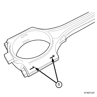
CAUTION: DO NOT STAMP the connecting rods during identification. The use of a scribe or a paint mark is acceptable.
NOTE: The 3.8L may have any combination of forged or cracked cap connecting rods. The cracked cap design is easily identified by the connecting rod cap bolts rather than the traditional forged connecting rod cap nuts. The cracked cap design also has a different tightening procedure and specification. The connecting rod caps must be paint marked or scribed to identify the accompanying connecting rod. All connecting rod caps ARE NOT inner changeable between connecting rods.
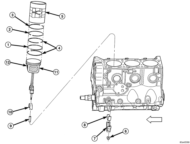
The pistons are made of cast aluminum alloy and are a strutless, short skirt design. The connecting rods have either the standard forged caps or forged cracked cap design. Both the cracked cap and forged cap connecting rod designs are interchangeable and may be found in any combination when mounted to the crankshaft. The difference between the two different rod caps, aside from design, is the tightening procedure and specification. The piston rings consist of two compression rings and a three piece oil ring. Piston pins connect the piston to the forged steel connecting rods. The piston pins are a press fit into the connecting rod small bore. The piston, pin and connecting rod are serviced as an assembly.
REMOVAL
NOTE: Refer to the connecting rod Description before beginning repair. (Refer to 9 - ENGINE/ENGINE BLOCK/PISTON & CONNECTING ROD - DESCRIPTION).
1. Disconnect negative cable from battery.
2. Remove the cylinder heads. (Refer to 9 - ENGINE/CYLINDER HEAD - REMOVAL)
3. Remove the oil pan. (Refer to 9 - ENGINE/LUBRICATION/OIL PAN - REMOVAL)
4. Remove the top ridge of cylinder bores with a reliable ridge reamer, if necessary, before removing pistons from cylinder block. Be sure to keep tops of pistons covered during this operation. Pistons and connecting rods must be removed from top of cylinder block. When removing piston and connecting rod assemblies from the engine, rotate crankshaft so that each connecting rod is centered in cylinder bore.
5. Inspect connecting rods and connecting rod caps for cylinder identification. Identify them with a paint mark or scribe, if necessary .
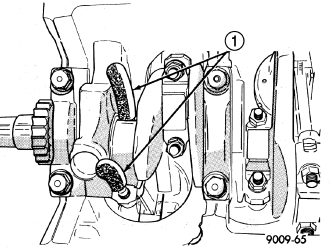
6. Remove connecting rod cap. Install connecting rod bolt protectors . on connecting rod bolts or use special tool #8189 to guide cracked connecting rod.
7. Remove each piston and connecting rod assembly out of the cylinder bore.
NOTE: Be careful not to nick crankshaft journals.
8. After removal, install bearing cap on the mating rod.
INSTALLATION
NOTE: Refer to the connecting rod Description before beginning repair. (Refer to 9 - ENGINE/ENGINE BLOCK/PISTON & CONNECTING ROD - DESCRIPTION).
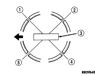
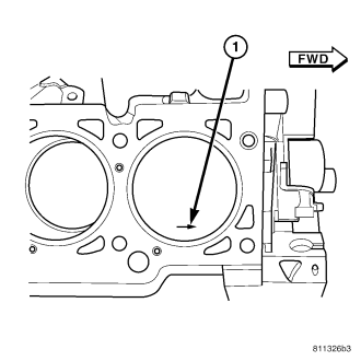
1. Before installing pistons and connecting rod assemblies into the bore, ensure that compression ring gaps are staggered so that neither is in line with oil ring rail gap and that the arrow on top of the piston is facing the front of the engine, if equipped .
2. Before installing the ring compressor, ensure the oil ring expander ends are butted and the rail gaps located as shown in .
3. Lubricate the piston and rings with clean engine oil. Position a ring compressor over the piston and rings, and tighten the compressor . Be sure position of rings does not change during this operation.
4. Position upper bearing onto connecting rod. Lubricate bearing with oil.
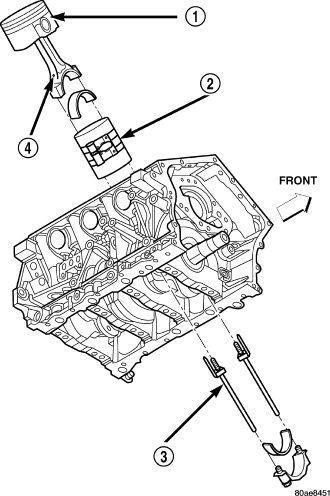
5. Install connecting rod bolt protectors (rubber hose or equivalent) . on the connecting rod bolts, or use special tool #8189 for cracked cap design
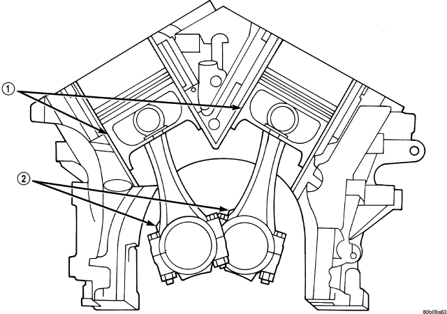
6. The pistons are marked with a “F” located near the piston pin, or an arrow on top of the piston. Install piston with this mark positioned to front of engine on both cylinder banks. The connecting rod oil squirt hole faces the major thrust (right) side of the engine block .
7. Rotate crankshaft until the connecting rod journal is located in the center of the cylinder bore. Insert connecting rod and piston into cylinder bore by tapping down on the piston using a hammer handle. At the same time, guide connecting rod into position on connecting rod journal..
8. Install lower bearing shell and the appropriate connecting rod cap .
9. Install connecting rod cap retaining nuts on cleaned and oiled rod bolts and tighten to 54 N·m (40 ft. lbs.) PLUS ¼ turn. Install connecting rod bolts and tighten to 7 N·m (5 ft. lbs) initially. Tighten the bolts an additional 21 N·m (15 ft. lbs.) and then turn each bolt 90° to final clamping load.
10. Repeat procedure for each piston and connecting rod installation.
11. Install the cylinder heads. (Refer to 9 - ENGINE/CYLINDER HEAD - INSTALLATION)
12. Install the oil pan. (Refer to 9 - ENGINE/LUBRICATION/OIL PAN - INSTALLATION)
13. Fill engine crankcase with proper oil to correct level.
14. Connect negative cable to battery.