For a complete wiring diagram, refer to the Wiring Information.
Theory of operation
The misfire detection monitor, software strategy in the Powertrain Control Module (PCM), is designed to detect an engine misfire. The PCM uses the Crankshaft (CKP) and Camshaft (CMP) Sensors to determine when an engine misfire event is occurring and determine individual misfire events by monitoring the crankshaft rotational speed. A misfire is nothing more than a lack of combustion, which can be caused by poor fuel quality or metering, low compression, lack of spark or unmetered air entering the engine. Other possible causes such as uncommanded Exhaust Gas Recirculating (EGR) flow can also cause a misfire. In the case of multiple cylinders misfiring or the PCM not determining the specific cylinder misfiring, P0300 Multiple Cylinder Misfire will set.
When Monitored:
Any time the engine is running and the adaptive numerator has been successfully updated.
Set Condition:
The threshold to set the fault is application specific; it is tied to the level of misfire that will cause emissions to increase to 1.5 times the standard or in some cases 1%. It is always a two trip fault above the calibrated RPM. It takes one fail to set a Pending Fault and two trips to set the MIL. Three good trips to turn off the MIL.
Diagnose and repair any other active component or circuit DTCs before continuing with this procedure.
2.
Turn the ignition on.
3.
With the scan tool, select View DTCs. Copy DTC and Freeze Frame information.
4.
Operate the vehicle under conditions similar to which the DTC was set.
5.
With the scan tool, view the Misfire Monitor to see which cylinders are effected.
NOTE:
It may be necessary to test drive the vehicle within the DTC monitoring conditions in order for this DTC to set or to show misfires on a particular cylinder. Try to repeat the conditions in which the fault originally set by reviewing the Freeze Frame data.
Are there excessive misfires shown or is the DTC pending at this time?
If there is a Camshaft Position Actuator Circuit Open DTC present along with this DTC, diagnose and repair that DTC before continuing with this test procedure.
When the engine is operating, do
not stand in direct line with the fan. Do not put your hands near
the pulleys, belts or fan. Do not wear loose clothing. Failure to
follow these instructions may result in possible serious or fatal
injury.
The fuel system is under a constant
pressure (even with the engine off). Before testing or servicing any
fuel system hose, fitting or line, the fuel system pressure must be
released. Failure to follow these instructions can result in possible
serious or fatal injury.
WARNING:
When the engine is operating, do
not stand in direct line with the fan. Do not put your hands near
the pulleys, belts or fan. Do not wear loose clothing. Failure to
follow these instructions may result in possible serious or fatal
injury.
NOTE:
Before continuing, visually and physically inspect the fuel delivery system for external leaks or damage. Repair/replace as necessary.
Before continuing, check the Fuel Pump Module harness connector terminals for corrosion, damage or terminal push out. Make sure the ground circuit is functional. Repair as necessary. Replace the Fuel Pump Module. (Refer to 14 - Fuel System/Fuel Delivery/MODULE, Fuel Pump - Removal)
.
When the engine is operating, do
not stand in direct line with the fan. Do not put your hands near
the pulleys, belts or fan. Do not wear loose clothing. Failure to
follow these instructions may result in possible serious or fatal
injury.
1.
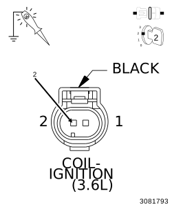
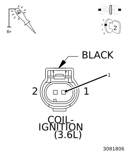
Using a 12-volt test light connected to a 12 volt source, probe the Coil Control circuit.
2.
Crank the engine for 5.0 seconds while observing the test light.
What is the condition of the test light while cranking the engine?
Brightly blinking
Replace the Ignition Coil in accordance with the Service Information.
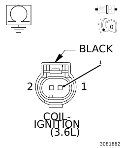
Using the wiring diagram/schematic as a guide, inspect the wiring and connectors between the Ignition Coil and the Powertrain Control Module (PCM).
2.
Look for any chafed, pierced, pinched, or partially broken wires.
3.
Look for broken, bent, pushed out or corroded terminals. Verify that there is good pin to terminal contact in the Ignition Coil and the Powertrain Control Module connectors.
4.
Refer to any Technical Service Bulletins that may apply.