HOUSING-HVAC
HOUSING-HVAC
| NOTE: |
3.6L LHD model shown in illustrations. Other models similar. |
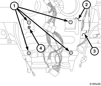 |
- Position the HVAC housing assembly (3) into the instrument panel support (2). Be certain that the housing alignment pin (4) is correctly located.
-
Install the four bolts (1) that secure the HVAC housing assembly to the center of instrument panel support. Tighten the bolts to 4 N·m (35 in. lbs.).
NOTE: If a foam seal on the top of the HVAC housing is deformed or damaged, the seal must be replaced.
-
Install the instrument panel ducts (Refer to 24 - Heating and Air Conditioning/Distribution/DUCT, Instrument Panel - Installation)
.
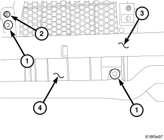
- Verify that the housing alignment pin (2) is correctly located in the passenger side of the instrument panel support (3).
- Install the two bolts (1) that secure the air inlet housing (4) to the instrument panel support. Tighten the bolts to 4 N·m (35 in. lbs.).
- Connect the instrument panel wire harness connectors to the evaporator temperature sensor, blower motor resistor, blower motor and the recirculation door actuator.
- Install the instrument panel cover (Refer to 23 - Body/Instrument Panel/COVER, Instrument Panel - Installation) .
-
Install the instrument panel (Refer to 23 - Body/Instrument Panel/PANEL, Instrument - Installation)
.
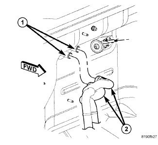
- Remove the previously installed plugs or caps and connect the heater hoses (2) to the heater core tubes (1).
-
Using cable-type spring clamp pliers or equivalent, correctly position the two hose clamps that secure the heater hoses to the heater core tubes and engage the clamps to the tubes.
- Remove the tape or plugs from the opened refrigerant line fittings and the expansion valve ports.
- Lubricate new O-ring seals with clean refrigerant oil and install them onto the refrigerant line fittings. Use only the specified O-rings as they are made of special materials compatible to the R-134a system. Use only refrigerant oil of the type recommended for the A/C compressor in the vehicle.
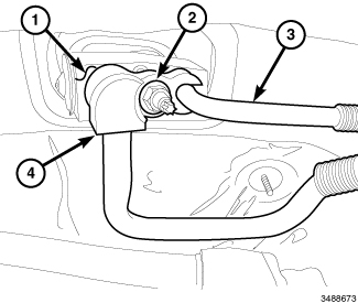
- Connect the A/C liquid line (3) and A/C suction line (4) onto the A/C expansion valve (1).
- Install the nut (2) that secures the A/C liquid and suction lines to the A/C expansion valve. Tighten the nut to 8 N·m (70 in. lbs.).
- On 3.6L engine models, install the upper intake manifold (Refer to 09 - Engine/Manifolds/MANIFOLD, Intake - Installation) .
- Install the engine trim cover.
- Reconnect the negative battery cable.
- If the heater core is being replaced, flush the cooling system (Refer to 07 - Cooling - Standard Procedure) .
- Refill the engine cooling system (Refer to 07 - Cooling - Standard Procedure) .
- Evacuate and charge the refrigerant system (Refer to 24 - Heating and Air Conditioning/Plumbing - Standard Procedure) .
-
Initiate the Actuator Calibration function using a scan tool (Refer to 28 - DTC-Based Diagnostics/HVAC - Standard Procedure)
.