PUMP, Fuel Injection
DESCRIPTION
DESCRIPTION
 |
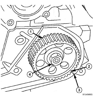
The pump is driven by the timing belt. Pressure is generated independently of the injection process. The pump is lubricated with diesel fuel and is not responsible for fuel injection timing. However, there is a mark on the high pressure fuel pump sprocket that must be aligned with a mark on the timing belt cover whenever the high pressure pump, sprocket, or timing belt have been removed. The high pressure fuel pump has a filter in the inlet side that is not serviceable.
OPERATION
OPERATION
High Pressure Pumping Plungers
The fuel quantity solenoid supples three high pressure pumping chambers. The pumping chambers have one way inlet valves that allow fuel to flow into the chambers. The valves then close during compression of the fuel and cause the high pressure fuel to overcome a ball and angled seat outlet valve.
All three pumping chambers are tied together in one circuit internal to the pump and provide high pressure fuel up to 1800 bar (26,106 psi) through a steel line, to the fuel rail.
The pump is driven at 1:1 engine speed and is not responsible for injection timing. The pump is only responsible for providing high pressure fuel while the PCM controls the injection timing.
The pump has a built in filter for filtering the fuel which is not serviceable. If the filter becomes plug or restricted affecting the performance of the vehicle then a P0087- Fuel Rail Pressure Too Low will set. The pump will have to be replaced if the filter gets plugged or restricted.
REMOVAL
REMOVAL
Cleanliness cannot be overemphasized
when handling or replacing diesel fuel system components. This especially
includes the fuel injectors, high-pressure fuel lines and fuel injection
pump. Very tight tolerances are used with these parts. Dirt contamination
could cause rapid part wear and possible plugging of fuel injector
nozzle tip holes. This in turn could lead to possible engine misfire.
Always wash/clean any fuel system component thoroughly before disassembly
and then air dry. Cap or cover any open part after disassembly. Before
assembly, examine each part for dirt, grease or other contaminants
and clean if necessary. When installing new parts, lubricate them
with clean engine oil or clean diesel fuel only.
CAUTION:
High-pressure lines
deliver diesel fuel under extreme pressure from the injection pump
to the fuel injectors. Use extreme caution when inspecting for high-pressure
fuel leaks. Fuel under this amount of pressure can penetrate skin
causing personal injury or death. Inspect for high-pressure fuel leaks
with a sheet of cardboard. Wear safety goggles and adequate protective
clothing when servicing fuel system.
WARNING:
- Disconnect negative battery cable.
- Center and lock the steering wheel.
- Remove the four nuts and the engine cover.
- Raise and support vehicle (Refer to 04 - Vehicle Quick Reference/Hoisting - Standard Procedure) .
- Remove the front lower splash shield.
- Drain the cooling system (Refer to 07 - Cooling - Standard Procedure) .
- Remove the two oil cooler return tube bolts.
- Remove the left wheel house splash shield (Refer to 23 - Body/Exterior/SHIELD, Splash - Removal) .
-
Remove the lower intermediate shaft-to-upper intermediate shaft pinch bolt and disconnect the intermediate shaft.
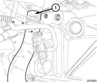
- Remove the oil cooler return hose (1) at water pump inlet tube.
- Remove the thermostat housing (Refer to 07 - Cooling/Engine/THERMOSTAT - Removal) .
- Remove the water inlet elbow (Refer to 07 - Cooling/Engine/TUBE, Water Inlet - Removal) .
- Remove the air cleaner body (Refer to 09 - Engine/Air Intake System/BODY, Air Cleaner - Removal) .
- Disconnect the coolant reservoir hose at radiator.
- Disconnect the upper radiator hose at radiator.
- Remove the cooling fan (Refer to 07 - Cooling/Engine/FAN, Cooling - Removal) .
- Remove the serpentine belt (Refer to 07 - Cooling/Accessory Drive/BELT, Serpentine - Removal) .
- Disconnect the Charge Air Cooler (CAC) outlet hose from the EGR air flow control valve.
- Disconnect the EGR air flow control valve harness connector.
-
Remove the generator (Refer to 08 - Electrical/8F - Engine Systems/Charging/GENERATOR - Removal)
.
- Remove timing belt (Refer to 09 - Engine/Valve Timing/BELT, Timing - Removal) .
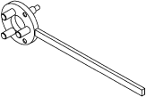
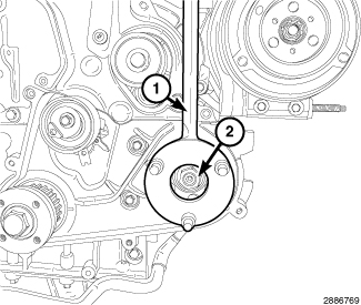
- Using Locking Tool VM.1055 (1), remove the injection pump sprocket nut (2).
-
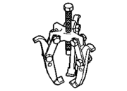
Attach a
Puller 1023 and remove sprocket from pump.
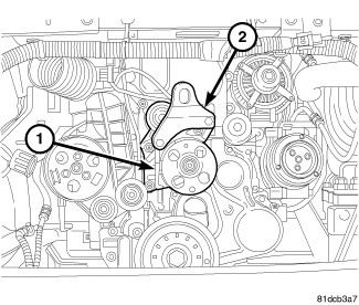
- Install the accessory drive idler pulley bracket (1). Tighten bolts finger tight.
- Install the front engine lift bracket (2). Tighten bolts finger tight.
- Remove the right side and left side lower engine mount nuts.
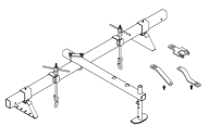
- Install the Fixture, Driveline Support 8534B .
- Raise the engine.
- Remove the high pressure feed tube at fuel rail.
-
Remove the bolt securing the high pressure feed tube to intake manifold.
-
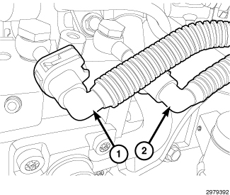
Disconnect the low pressure supply (1) and return (2) lines at high pressure pump.
- Detach the fuel line routing clip at the left engine mount bracket.
- Disconnect the fuel quantity solenoid harness connector.
-
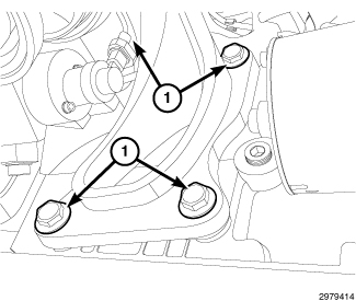
Remove the four bolts (1) and the left engine mount and bracket.
NOTE: Fuel quantity solenoid removed for clarity.
-
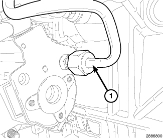
Remove the high-pressure fuel line (1) at rear of pump and fuel rail.
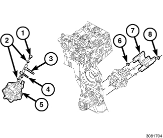
- Remove nuts (8) and the blocker plate (7).
- Remove nuts (6) and fuel injection pump (5).
-
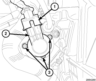
If necessary, Remove banjo bolts (1) and the fuel supply (3) and return (4) fittings from pump (5).
-
If necessary, remove screws (3) and the fuel quantity solenoid (2).
INSTALLATION
INSTALLATION
Cleanliness cannot be overemphasized
when handling or replacing diesel fuel system components. This especially
includes the fuel injectors, high-pressure fuel lines and fuel injection
pump. Very tight tolerances are used with these parts. Dirt contamination
could cause rapid part wear and possible plugging of fuel injector
nozzle tip holes. This in turn could lead to possible engine misfire.
Always wash/clean any fuel system component thoroughly before disassembly
and then air dry. Cap or cover any open part after disassembly. Before
assembly, examine each part for dirt, grease or other contaminants
and clean if necessary. When installing new parts, lubricate them
with clean engine oil or clean diesel fuel only.
CAUTION:
|
-
If necessary, Install the fuel quantity solenoid (2). Tighten screws (3) to 7 N·m (62 in. lbs.).
-
If necessary, using new sealing washers (2) and install the banjo bolts (1) the fuel supply (3) and return (4) fittings onto pump (5). Tighten banjo bolts to 28 N·m (21 ft. lbs.).
NOTE: Be sure pump is fully seated before tightening mounting nuts.
- Install the fuel injection pump (5). Tighten nuts (6) to 25 N·m (18 ft. lbs.).
-
Install the blocker plate (7). Tighten nuts (8) to 25 N·m (18 ft. lbs.).
NOTE: Fuel quantity solenoid removed for clarity.
- Install the new high-pressure fuel tube (1) to rear of pump and fuel rail.
- Tighten the high pressure fuel feed tube at the high pressure pump (1) to 28 N·m (20 ft. lbs.).
- Tighten the high pressure fuel feed tube at the fuel rail to 5 N·m (44 in. lbs) plus an additional 75 degrees.
-
Install fuel tube clamp bolt. Tighten to 15 N·m (133 in. lbs.).
- Install the left engine mount and bracket. Tighten bolts (1) to 100 N·m (74 ft. lbs.).
- Connect the fuel quantity solenoid harness connector.
-
Attach the fuel line routing clip at the left engine mount bracket.
-
Connect the low pressure supply (1) and return (2) lines at high pressure pump.
- Lower the engine.
- Remove the Fixture, Driveline Support 8534B .
- Install the right side and left side lower engine mount nuts. Tighten nuts to 54 N·m (40 ft. lbs.).
- Remove the front engine lift bracket (2).
-
Remove the accessory drive idler pulley bracket (1).
-
Position sprocket (1) onto pump shaft and install nut (4) finger tight.
- Using Locking Tool VM.1055 (1), tighten injection pump sprocket nut (2) to 88 N·m (65 ft. lbs.).
- Install timing belt (Refer to 09 - Engine/Valve Timing/BELT, Timing - Installation) .
- Install the generator (Refer to 08 - Electrical/8F - Engine Systems/Charging/GENERATOR - Installation) .
- Connect the EGR air flow control valve harness connector.
- Connect the Charge Air Cooler (CAC) outlet hose from the EGR air flow control valve.
- Install the serpentine belt (Refer to 07 - Cooling/Accessory Drive/BELT, Serpentine - Installation) .
- Install the cooling fan (Refer to 07 - Cooling/Engine/FAN, Cooling - Installation) .
- Connect the upper radiator hose at radiator.
- Connect the coolant reservoir hose at radiator.
- Install the air cleaner body (Refer to 09 - Engine/Air Intake System/BODY, Air Cleaner - Installation) .
- Install the water inlet elbow (Refer to 07 - Cooling/Engine/TUBE, Water Inlet - Installation) .
-
Install the thermostat housing (Refer to 07 - Cooling/Engine/THERMOSTAT - Installation)
.
- Install the oil cooler return hose (1) at water pump inlet tube.
- Install the two oil cooler return tube bolts. Tighten bolts in to 15 N·m (133 in. lbs.).
- Install the front lower splash shield.
- Lower vehicle.
- Fill the cooling system (Refer to 07 - Cooling - Standard Procedure) .
- Install the engine cover and securely tighten the four nuts.
- Connect the negative battery cable.
- Remove the steering wheel lock.
-
Start engine and check for fuel leaks.