Frame
- USE OF HEAT DURING REPAIR
- WARNINGS
- FRONT FRAME RAIL TIP REPLACEMENT
- REAR CROSSMEMBER
- WELD NUT SERVICE
- FRAME DIMENSIONS
- WELD PROCESS
USE OF HEAT DURING REPAIR
WARNINGS
Use an Occupational Safety and Health Administration (OSHA) approved breathing filter, when spraying paint or solvents in a confined area. Failure to follow these instructions may result in possible serious or fatal injury.
WARNING:
Restraint Warnings
To avoid potential physical injury, or damage to sensitive electronic circuits and systems, always disconnect and isolate the battery negative (ground) cable and the positive cable, then ground the positive cable to discharge the ORC capacitor before performing any welding operations on the vehicle. Failure to take the proper precautions could result in accidental airbag deployment, possible damage to the Supplemental Restraint System (SRS) circuits and components, and possible damage to other electronic circuits and components. Whenever a welding process is being performed within 30 cm (12 in) of an electronic module/harness, then that module/harness should be relocated out of the way, or disconnected. Always protect against component or vehicle damage from weld spatter by using weld blankets and screens. Failure to follow these instructions may result in serious or fatal injury.
WARNING:
To avoid serious or fatal injury on vehicles equipped with the Supplemental Restraint System (SRS), never attempt to repair the electrically conductive circuits or wiring components related to the SRS for which there is no MOPAR wiring repair kit. It is important to use ONLY the recommended splicing kit and procedure. For applicable and available MOPAR wiring repair kits, please visit the MOPAR Connector Web Site at the following address on the internet: (http://dto.vftis.com/mopar/disclaimer.asp). Inappropriate repairs can compromise the conductivity and current carrying capacity of those critical electrical circuits, which may cause SRS components not to deploy when required, or to deploy when not required. Only minor cuts or abrasions of wire and terminal insulation where the conductive material has not been damaged, or connector insulators where the integrity of the latching and locking mechanisms have not been compromised may be repaired using appropriate methods.
WARNING:
To avoid serious or fatal injury
during and following any seat belt or child restraint anchor service,
carefully inspect all seat belts, buckles, mounting hardware, retractors,
tether straps, and anchors for proper installation, operation, or
damage. Replace any belt that is cut, frayed, or torn. Straighten
any belt that is twisted. Tighten any loose fasteners. Replace any
belt that has a damaged or ineffective buckle or retractor. Replace
any belt that has a bent or damaged latch plate or anchor plate. Replace
any child restraint anchor or the unit to which the anchor is integral
that has been bent or damaged. Never attempt to repair a seat belt
or child restraint component. Always replace damaged or ineffective
seat belt and child restraint components with the correct, new and
unused replacement parts listed in the Chrysler Mopar® Parts Catalog.
Failure to follow these instructions may result in possible serious
or fatal injury.
WARNING:
To avoid serious or fatal injury on vehicles equipped with airbags, disable the Supplemental Restraint System (SRS) before attempting any steering wheel, steering column, airbag, Occupant Classification System (OCS), seat belt tensioner, impact sensor or instrument panel component diagnosis or service. Disconnect and isolate the battery negative (ground) cable, then wait two minutes for the system capacitor to discharge before performing further diagnosis or service. This is the only sure way to disable the SRS. Failure to follow these instructions may result in accidental airbag deployment.
WARNING:
To avoid potential physical injury
or damage to sensitive electronic circuits and systems, always disconnect
and isolate the battery negative (ground) cable and the positive cable,
then ground the positive cable to discharge the Occupant Restraint
Controller (ORC) capacitor before performing any welding operations
on the vehicle. Failure to take the proper precautions could result
in accidental airbag deployment, possible damage to the Supplemental
Restraint System (SRS) circuits and components, and possible damage
to other electronic circuits and components. Whenever a welding process
is being performed within 12 inches (30 centimeters) of an electronic
module or wiring harness, then that module or harness should be relocated
out of the way, or disconnected. Always protect against component
or vehicle damage from weld spatter by using weld blankets and screens.
WARNING:
To avoid serious or fatal injury,
do not attempt to dismantle an airbag unit or tamper with its inflator.
Do not puncture, incinerate or bring into contact with electricity.
Do not store at temperatures exceeding 93° C (200° F). An airbag inflator
unit may contain sodium azide and potassium nitrate. These materials
are poisonous and extremely flammable. Contact with acid, water, or
heavy metals may produce harmful and irritating gases (sodium hydroxide
is formed in the presence of moisture) or combustible compounds. An
airbag inflator unit may also contain a gas canister pressurized to
over 17.24 kPa (2500 psi). Failure to follow these instructions may
result in possible serious or fatal injury.
WARNING:
To avoid serious or fatal injury when handling a seat belt tensioner retractor. Exercise proper care to keep fingers out from under the retractor cover and away from the seat belt webbing where it exits from the retractor cover. Failure to follow these instructions may result in possible serious or fatal injury.
WARNING:
To avoid serious or fatal injury,
replace all Supplemental Restraint System (SRS) components only with
parts specified in the Chrysler Mopar® Parts Catalog. Substitute parts
may appear interchangeable, but internal differences may result in
inferior occupant protection.
WARNING:
To avoid serious or fatal injury,
the fasteners, screws, and bolts originally used for the Supplemental
Restraint System (SRS) components must never be replaced with any
substitutes. These fasteners have special coatings and are specifically
designed for the SRS. Anytime a new fastener is needed, replace it
with the correct fasteners provided in the service package or specified
in the Chrysler Mopar® Parts Catalog.
WARNING:
To avoid serious or fatal injury
when a steering column has an airbag unit attached, never place the
column on the floor or any other surface with the steering wheel or
airbag unit face down. Failure to follow these instructions may result
in possible serious or fatal injury.
WARNING:
FRONT FRAME RAIL TIP REPLACEMENT
 |
|
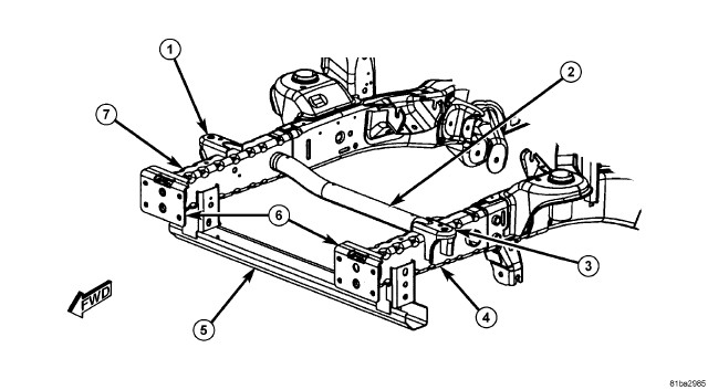
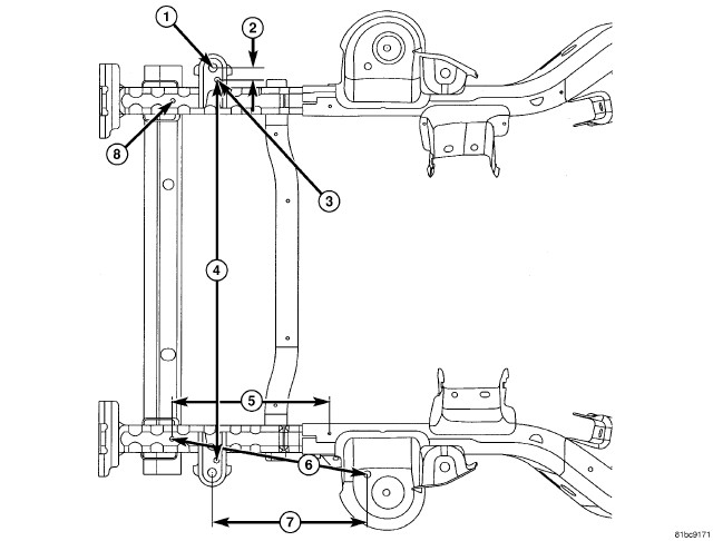
1 - FONT END SHEET METAL (FESM) BRACKET 2 - CROSS-FRAME TUBE 3 - FESM BRACKET 4 - LEFT FRAME RAIL 5 - COMPATIBILITY BEAM 6 - BUMPER MOUNTING BRACKETS 7 - RIGHT FRAME RAIL |
- Mount the vehicle on appropriate frame correction equipment (“frame rack”) and using a three-dimensional measuring system measure frame/body and correct to vehicle specifications.
-
Release welds holding
compatibility beam (5) brackets to rails (4 and 7) and remove – if
compatibility beam is to be replaced also, the brackets only need
to be removed from the undamaged rail.
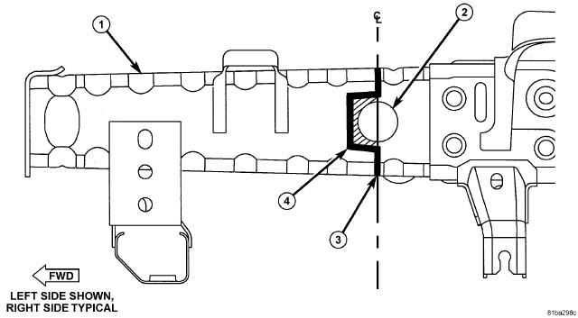
- At the centerline of the cross-frame tube, use a reciprocating saw to make a vertical cut (3) through the frame rail to the tube (2) from both the top and bottom.
- Using either a reciprocating saw or a plasma cutter, cut forward of the tube (4) to release the rail (1) from the tube (2).
- Grind off any remaining rail or weld attached to the tubular crossmember forward of the original vertical cuts in preparation for the replacement part.
-
Any cuts into the tubular
crossmember should be welded and dressed smooth before proceeding.
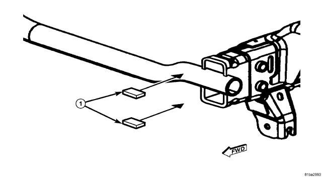
- From the removed rail, cut weld-backers (1) which will fit snugly into the original frame at the cut location. Position these backers so 12.7 mm (1/2 inch) protrudes from the section location.
- Cut the service part vertically at the same location as the original frame.
- Clean and de-burr all cut edges, remove e-coat within 25.4 mm (1 inch) of the joint from the inside and outside of all the surfaces.
- Make sure that a slight bevel is created at the butt-weld joint to allow complete weld penetration.
-
Refer to the weld chart (Refer to 13 - Frame and Bumpers/Frame
- Specifications)
for proper weld rod and approximate welder
settings, and adjust the welder to create a proper weld bead.
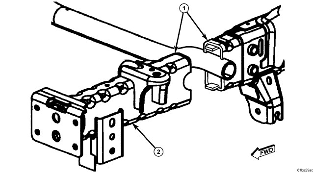
- Position new (cut) rail tip (2) in proper position and tack-weld in place (1).
-
Weld replacement tip
in place using a skip-stitch process – welding in 50.8 mm (2 inch)
increments, weld the rail on opposing sides to avoid distortion, Also
allow the rail to cool between the welding operations.
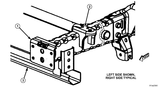
- Position and tack-weld FESM bracket (2), bumper mounting bracket (1), and compatibility beam (3).
- When dimensional accuracy is confirmed, finish weld all components using the original weld locations as a guideline.
-
If the FESM brackets
and bumper mounting brackets were not pierced, create the appropriate
piercings at this time.
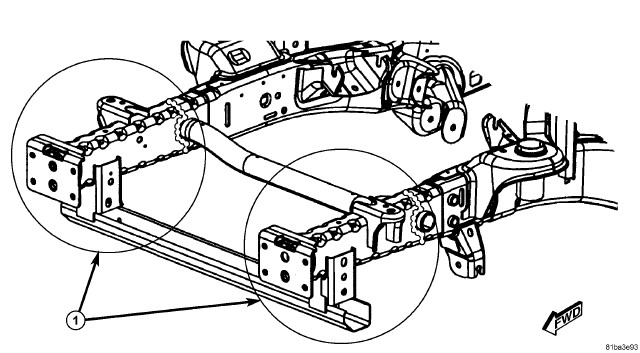
- Cosmetically dress welds without removing any base metal – a skim coat of filler may be utilized for an improved cosmetic appearance.
- Refinish all components to a production appearance.
- On all areas (1) inaccessible to the refinish operation, apply a creeping type rust proofing material ensuring 100% coverage. Be especially focused on those areas where welding may have burned off the original corrosion protection.
Bracket Locations And Modifications
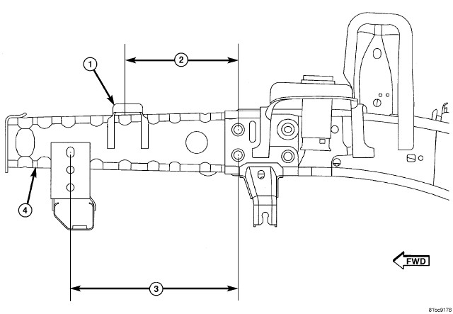 BRACKET LOCATIONS - SIDE VIEW |
|
1 - FESM BRACKET 2 - 239.6 mm (9.43 inch) 3 - 335.1 mm (13.2 inch) 4 - FRAME RAIL TIP |
REAR CROSSMEMBER
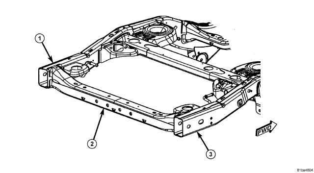 |
- Mount the vehicle on appropriate frame correction equipment (“frame rack”) and using a three-dimensional measuring system measure frame/body and correct to vehicle specifications, (Refer to 13 - Frame and Bumpers/Frame - Specifications) .
- Remove rear bumper components, (Refer to 13 - Frame and Bumpers/Bumpers/BUMPER, Rear - Removal) .
- Remove hitch receiver or tow hook if equipped, (Refer to 13 - Frame and Bumpers/Frame/HITCH, Trailer - Removal) .
-
Release rear body mount fasteners, and loosen remaining body fasteners to allow lifting the body upward providing work access, (Refer to 23 - Body/Exterior/ISOLATOR, Body - Removal)
.
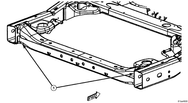
- Using a reciprocating saw, or equivalent, cut the crossmember close to the welds to the side rails and body mount brackets (1) and remove (each side of crossmember has a total of 7 welds).
- Using an angle grinder, grind off remaining crossmember and weldments.
- Dress new crossmember at weld locations so that a very shallow bevel is created and remove any e-coat, inside and out, on replacement part within 25.4 mm (1”) of weld zones as best possible.
-
Refer to the weld chart for proper weld rod and approximate welder settings, then using the old crossmember adjust the welder to create a proper weld bead, (Refer to 13 - Frame and Bumpers/Frame - Specifications)
.
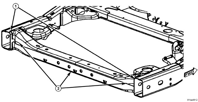
- Install the crossmember and locate using three-dimensional measuring equipment.
- When proper, tack-weld crossmember securely in position (1).
- Complete weld installation of crossmember ensuring proper weld penetration.
- Clean welded area of any burned coatings or spatter.
- Apply refinish materials to exterior of crossmember and side rails (2) to restore appearance and corrosion protection.
- Apply inner panel anti-corrosion material inside crossmember.
- Install the rear body mount fasteners and tighten all fasteners, (Refer to 23 - Body/Exterior/ISOLATOR, Body - Installation) .
- Install hitch receiver/tow hook, (Refer to 13 - Frame and Bumpers/Frame/HITCH, Trailer - Installation) .
- Install bumper components, (Refer to 13 - Frame and Bumpers/Bumpers/BUMPER, Rear - Installation) .
WELD NUT SERVICE
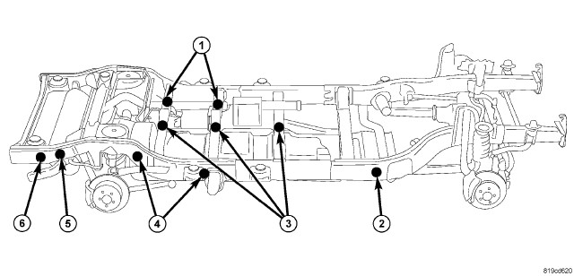 Figure 1 - SERVICE LOCATIONS |
| 1 - THREE M10 FUEL VAPOR CANISTER CROSSMEMBER NUTS | – ACCESS HOLES LOCATED ON TOP OF CROSSMEMBERS |
| 2 - TWO M12 TRANSMISSION SKID PLATE CROSSMEMBER NUTS | – ACCESS HOLES LOCATED ON INSIDE OF FRAME RAILS |
| 3 - M12 FUEL TANK CROSSMEMBER NUTS (SWB has 2, LWB has 3) | – ACCESS HOLES LOCATED ON TOP OF CROSSMEMBERS |
| 4 - M12 FUEL TANK FRAME RAIL NUTS | – ACCESS HOLES LOCATED ON OUTSIDE OF FRAME RAIL |
| 5 - TWO M10 REAR STABILIZER NUTS | – ACCESS HOLES LOCATED ON THE OUTSIDE OF FRAME RAILS |
| 6 - FOUR M10 STANDARD REAR BUMPER BRACKET NUTS | – ACCESS THROUGH REAR OF FRAME RAILS |
Vapor Canister
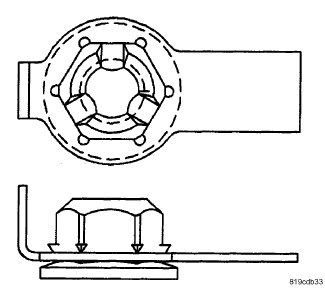 TYPE 1 NUT |
|
M10 Locations: Vapor Canister (1) M12 Locations: Fuel Tank Crossmember (3) |
- Using a cut off wheel or equivalent, remove the vapor canister support bolt with the damaged weld nut.
- Remove the damaged weld nut from the access hole in the top of the crossmember (1).
-
Position a new M10
type 1 nut into the access hole and install the vapor canister bolt, (Refer to 25 - Emissions Control/Evaporative
Emissions/CANISTER, Vapor - Installation)
.
Fuel Tank
TYPE 1 NUT |
|
M10 Locations: Vapor Canister (1) M12 Locations: Fuel Tank Crossmember (3) |
- Using a cut off wheel or equivalent, remove the fuel tank support bolt with the damaged weld nut.
- If necessary remove the damaged weld nut from the access hole in the top of the crossmember (3).
- If necessary remove the damaged weld nut from the access hole in the frame rail (4).
-
If necessary, position
a new M12 type 1 nut into the access hole in the crossmember (3) and
install the fuel tank bolt, (Refer to 14 - Fuel System/Fuel Delivery/TANK, Fuel - Installation)
.
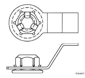
TYPE 2 NUT
M10 Locations:
Stabilizer bar (5)
M12 Locations:
Fuel Tank Frame Rail (4)
Transmission Skid Plate (2)
-
If necessary, position
a new M12 type 2 nut into the access hole in the frame rail (4) and
install the fuel tank bolt.
Rear Bumper Bracket
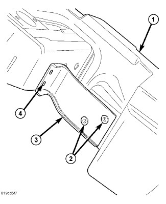 |
- Remove the rear bumper, (Refer to 13 - Frame and Bumpers/Bumpers/BUMPER, Rear - Removal) .
- Using a cut off wheel or equivalent, remove the rear bumper support bracket bolt (4) with the damaged weld nut.
- Remove the damaged weld nut from the rear of the frame rail.
- Install a standard M10 nut into the end of the frame rail using a box end wrench and install the bracket bolt.
- Tighten the bolt to 55 N·m (40.5 ft. lbs.).
-
Install the rear bumper, (Refer to 13 - Frame and Bumpers/Bumpers/BUMPER,
Rear - Installation)
.
Rear Stabilizer Bar
TYPE 2 NUT |
|
M10 Locations: Stabilizer bar (5) M12 Locations: Fuel Tank Frame Rail (4) Transmission Skid Plate (2) |
- Using a cut off wheel or equivalent, remove the rear stabilizer bolt with the damaged weld nut.
- Remove the damaged weld nut from the access hole in the in the frame rail (5).
-
Position a new M10
type 2 nut into access hole in the frame rail and install the stabilizer
bar bolt, (Refer to 17 - Rear
Suspension/STABILIZER BAR, Rear Suspension - Installation)
.
Transmission Skid Plate
TYPE 2 NUT |
|
M10 Locations: Stabilizer bar (5) M12 Locations: Fuel Tank Frame Rail (4) Transmission Skid Plate (2) |
- Using a cut off wheel or equivalent, remove the transmission skid plate bolt with the damaged weld nut.
- Remove the damaged weld nut from the access hole in the frame rail (2).
-
Position a new M12
type 2 nut into the access hole in the frame rail and install the
skid plate bolt. (Refer to 13
- Frame and Bumpers/Under Body Protection/PLATE, Skid - Installation)
FRAME DIMENSIONS
Frame dimensions are listed in metric scale. All dimensions are from center to center of Principle Locating Point (PLP), or from center to center of PLP and fastener location.
VEHICLE PREPARATION:
Position the vehicle on a level work surface. Using screw or bottle jacks, adjust the vehicle PLP heights to the specified dimension above a level work surface. Vertical dimensions can be taken from the work surface to the locations indicated were applicable.
Index
|
DESCRIPTION |
FIGURE |
|---|---|
|
PLAN VIEW - TWO DOOR JK ONLY |
|
|
SIDE VIEW - TWO DOOR JK ONLY |
|
|
PLAN VIEW - FOUR DOOR JK ONLY |
|
|
SIDE VIEW - FOUR DOOR JK ONLY |
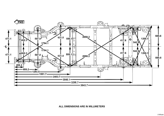 Figure 1 - PLAN VIEW - TWO DOOR JK ONLY |
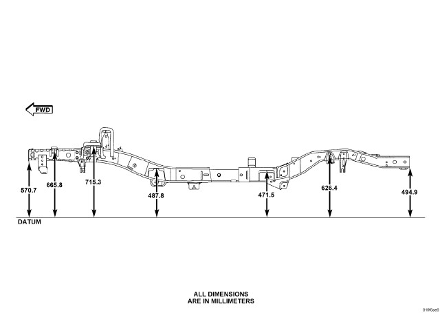 Figure 2 - SIDE VIEW - TWO DOOR JK ONLY |
 Figure 3 - PLAN VIEW - TWO AND FOUR DOOR J8 |
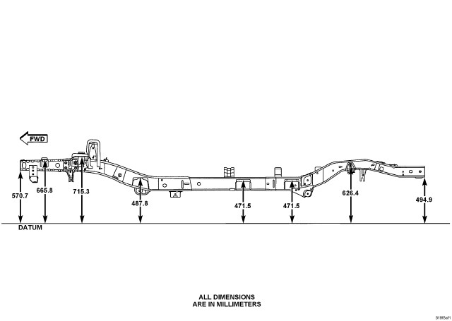 Figure 4 - SIDE VIEW - TWO AND FOUR DOOR J8 |
WELD PROCESS
All welds should conform to the Chrysler LLC vehicle engineering process standard PS 9472.
CAUTION:
WELDING PARAMETERS
|
WELDING PROCESS |
FLUX CORED ARC |
GAS METAL ARC (MIG)* |
SHIELDED METAL ARC (STICK) |
|---|---|---|---|
|
Material Thickness |
3.7 mm to 4.2 mm |
3.7 mm to 4.2 mm |
3.7 mm to 4.2 mm |
|
Electrode Type |
Lincoln Electrical Co. Product #: NR-211 MP (Do Not Substitute) |
AWS ER70S-6 (Do Not Substitute) |
** AWS E 7018 |
|
Electrodes Size Inches |
.045 Tubular |
.035 Solid |
3/32" |
|
Electrode Stick Out |
3/8" - 1/2" |
1/2" - 5/8" |
N/A |
|
Polarity |
Electrode "-" Work Piece "+" |
Electrode "+" Work Piece "-" |
Electrode "+" Work Piece "-" |
|
Shielding Gas |
Self Shielded |
75% Ar 25% CO2 |
Self Shielded |
|
Gas Flow Rate |
N/A |
25 - 35 CFM |
N/A |
|
Wire Feed Speed (inches per minute) |
110 - 130 Vertical Down 70 - 90 Flat AND Overhead |
245 - 250 Vertical Down 210 - 225 Flat AND Overhead |
N/A |
|
Approximate Amperage |
|||
|
Vertical |
110 - 130 |
175 |
85 (3/32" Diameter) |
|
Flat AND Overhead |
70 - 90 |
155 |
90 (3/32" Diameter) |
|
Voltage |
15 - 18 |
19 - 20 |
N/A |
|
Direction of Welding |
|||
|
Vertical |
Vertical Down Hill (only) |
Vertical Down Hill (only) |
Vertical - Up Hill (only) |
|
Flat AND Overhead |
Flat - Push or Drag |
Flat - Push or Drag |
Flat - Drag |
*First choice - Gas Metal Arc Welding Process: Butt joints - apply two layers (passes) of weld metal. First pass should only fill approximately ½ the thickness. Vertical position welds - maintain electrode wire at leading edge of weld puddle while traveling down hill to produce maximum penetration into the sleeve. These techniques work for FCAW as well.
**E7018 new electrodes may be exposed to the atmosphere for up to ten hours with no harmful effect. Reconditioning schedules should come from the manufacturer.