GAUGE PACK, Instrument Cluster
DESCRIPTION
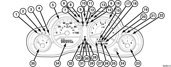 |
The instrument cluster assembly houses 4 analog gauges and has provisions for up to 25 International Control and Display Symbol icon indicators, (Refer to 08 - Electrical/8J - Instrument Cluster/INDICATORS, Instrument Cluster - Description) that are all controlled by the Cab Compartment Node (CCN) and standard on all models. The gauge graphics are white and gray against a black field except for a single red graduation at the high end of the gauge scale on both the engine temperature and fuel level gauges, and several red graduations at the high end of the gauge scale on the tachometer that designate the red line area, making them clearly visible within the instrument cluster in daylight. When illuminated by the cluster illumination lighting, the white and gray text and graphics as well as the red graphics still appear the same, the red gauge needles have internal optical illumination. Gauge illumination is provided by dimmer controlled Light Emitting Diode (LED) units soldered onto the CCN circuit board. The Gauge set and indicators shown above are an integrated part of the CCN, therefore are only serviced as a unit with the instrument cluster. The cluster lens and the cluster hood and mask unit are the only components of the instrument cluster assembly that can be serviced separately
The instrument cluster includes the following analog gauges:
ENGINE TEMPERATURE
The standard equipment engine temperature gauge is located on the right side of the instrument cluster, just to the right and below the tachometer. The gauge consists of a movable gauge needle or pointer controlled by the CCN circuitry and a fixed 90 degree gauge scale on the cluster overlay that reads left-to-right from C (or Cold) to H (or Hot). An International Control and Display Symbol icon for Engine Coolant Temperature is located on the cluster overlay, directly above the hub of the gauge needle. (Refer to 00 - Vehicle Data/Vehicle Information/International Vehicle Control and Display Symbols - Description) for more information.
FUEL LEVEL
A fuel gauge is standard equipment on all instrument clusters. This gauge is located on the left side of the instrument cluster, just to the left and below the speedometer. Similar to the engine temperature gauge, the fuel level gauge consists of a movable gauge needle or pointer controlled by the CCN circuitry and a fixed 90 degree gauge scale on the cluster overlay that reads left-to-right from E (or Empty) to F (or Full). The International Control and Display Symbol icon for Fuel is located on the cluster overlay, directly above the hub of the gauge needle. An arrowhead pointed to the left side of the vehicle is imprinted on the cluster overlay next to the Fuel icon on the gauge to provide the driver with a reminder as to the location of the fuel filler access.
SPEEDOMETER
Standard equipment on all instrument clusters, the speedometer is located to the left of center in the instrument cluster, between the tachometer and the fuel gauge. The speedometer consists of a movable gauge needle or pointer controlled by the instrument cluster circuitry and a fixed 185 degree primary scale on the gauge dial face that reads left-to-right either from 0 to 100 or 110 mph, or from 0 to 200 km/h, depending upon the market for which the vehicle is manufactured.
Each version also has a secondary inner scale on the gauge dial face that provides the equivalent opposite units from the primary scale. Text appearing on the cluster overlay above the hub of the speedometer needle and below the primary scale abbreviates the unit of measure for the primary scale (either MPH or km/h), and text above the hub of the speedometer needle and below the secondary scale indicates the unit of measure for that scale.
TACHOMETER
The standard equipment tachometer is located to the right of center in the instrument cluster, between the speedometer and the coolant temperature gauge. The tachometer consists of a movable gauge needle or pointer controlled by the instrument cluster circuitry and a fixed 185 degree scale on the gauge dial face that reads left-to-right either from 0 to 7 for vehicles with a gasoline engine, or from 0 to 5 for vehicles with a diesel engine. The text RPM X 1000 imprinted on the cluster overlay directly above the hub of the tachometer needle identifies that each number on the tachometer scale is to be multiplied by 1000 rpm.
OPERATION
GAUGES
All gauges receive battery current through the Cab Compartment Node (CCN) circuitry only when the ignition switch is in the ON or START positions. With the ignition switch in the OFF position battery current is not supplied to any gauges, and the CCN circuitry is programmed to move all of the gauge needles back to the low end of their respective scales. Therefore, the gauges do not accurately indicate any vehicle condition unless the ignition switch is in the ON or START positions.
All of the CCN gauges are driven by stepper motors. Two fixed electromagnetic coils are located within each gauge. These coils are wrapped at right angles to each other around a movable permanent magnet. The movable magnet is suspended within the coils on one end of a pivot shaft, while the gauge needle is attached to the other end of the shaft. One of the coils has a fixed current flowing through it to maintain a constant magnetic field strength. Current flow through the second coil changes, which causes changes in its magnetic field strength. The current flowing through the second coil is changed by the CCN circuitry in response to messages received over the CAN data bus. The gauge needle moves as the movable permanent magnet aligns itself to the changing magnetic fields created around it by the electromagnets.
The gauges are diagnosed using the CCN self-diagnostic test (Refer to 08 - Electrical/8J - Instrument Cluster - Diagnosis and Testing) . Proper testing of the CAN data bus and the electronic data bus message inputs to the CCN that control each gauge require the use of a diagnostic scan tool. Refer to the appropriate diagnostic information.
ENGINE TEMPERATURE
This gauge is controlled by the CCN circuit board based upon programming and electronic messages received from the Powertrain Control Module (PCM) over the CAN data bus.
The engine coolant temperature gauge is a stepper motor gauge that receives battery current on the CCN electronic circuit board through the fused ignition switch output (run-start) circuit whenever the ignition switch is in the ON or START positions. The CCN is programmed to move the gauge needle back to the low end of the scale after the ignition switch is turned to the Off position. The CCN circuitry controls the gauge needle position and provides the following features:
- Engine Temperature Message - Each time the CCN receives an electronic engine temperature message from the PCM indicating the temperature is between the low end of normal [about 41 °C (105 °F) for gasoline engines, or about 28 °C (82 °F) for diesel engines] and the high end of normal [about 124 °C (255 °F) for gasoline engines, or about 118 °C (244 °F) for diesel engines], the gauge needle is moved to the actual relative temperature position on the gauge scale.
- Engine Temperature Low Message - Each time the CCN receives an electronic engine temperature message from the PCM indicating the temperature is low [at or below about 40 °C (104 °F) for gasoline engines, or about 27 °C (81 °F) for diesel engines], the gauge needle is held below the graduation on the far left end of the gauge scale. The gauge needle remains below the low end of the gauge scale until the CCN receives a message from the PCM indicating that the temperature is above the low end of normal, or until the ignition switch is turned to the OFF position, whichever occurs first.
- Engine Temperature High or Critical Message - Each time the CCN receives an electronic engine temperature message from the PCM indicating the temperature is high [at or above about 127 °C (261 °F) for gasoline engines, or about 118 °C (244 °F) for diesel engines], the gauge needle is moved to the red graduation at the high end of the gauge scale, the engine temperature indicator is illuminated and a single chime tone is sounded. The gauge needle remains at the red graduation and the engine temperature indicator remains illuminated until the CCN receives a message from the PCM indicating that the temperature is below about 124 °C (255 °F) for gasoline engines, or about 115 °C (239 °F) for diesel engines, or until the ignition switch is turned to the OFF position, whichever occurs first. The chime tone feature will only repeat during the same ignition cycle if the engine temperature indicator is cycled OFF and then ON again by the appropriate messages from the PCM.
- Communication Error - If the CCN fails to receive an engine temperature message, it will hold the gauge needle at the last indication for about five seconds or until the ignition switch is turned to the OFF position, whichever occurs first. After five seconds, the CCN will move the gauge needle to the low end of the gauge scale.
The PCM continually monitors the engine coolant temperature sensor to determine the engine operating temperature. The PCM then sends the proper engine coolant temperature messages to the CCN. For further diagnosis of the engine coolant temperature gauge or the CCN circuitry that controls the gauge, (Refer to 08 - Electrical/8J - Instrument Cluster - Diagnosis and Testing) . If the CCN turns on the engine temperature indicator due to a high engine temperature gauge reading, it may indicate that the engine or the engine cooling system requires service. The engine coolant temperature gauge is serviced as a unit with the instrument cluster.
FUEL GAUGE
The fuel gauge gives an indication to the vehicle operator of the level of fuel in the fuel tank. This gauge is controlled by the CCN circuit board based upon programming and a hard wired input received from the fuel level sending unit on the fuel pump module in the fuel tank.
The fuel gauge is a stepper motor design gauge that receives battery current on the CCN electronic circuit board through the fused ignition switch output (run-start) circuit whenever the ignition switch is in the On or Start positions. The CCN is programmed to move the gauge needle back to the low end of the scale after the ignition switch is turned to the Off position. The CCN circuitry controls the gauge needle position and provides the following features:
- Fuel Level Message - The TIPM provides a constant current source to the fuel level sending unit and monitors a return input on a fuel level sense circuit. The resistance through the fuel level sending unit increases as the fuel level rises and decreases as the fuel level falls causing changes in the fuel level sense input voltage. The TIPM then sends the appropriate electronic fuel level messages to the CCN. The CCN programming applies an algorithm to calculate the proper fuel gauge needle position based upon the fuel level message input, then moves the gauge needle to the proper relative position on the gauge scale. This algorithm is used to dampen gauge needle movement against the negative effect that fuel sloshing within the fuel tank can have on accurate inputs from the fuel tank sending unit to the TIPM.
- Less Than 11 Percent Tank Full Message - Each time the fuel level message to the CCN indicates the fuel tank is about 11 percent full or less for 10 consecutive seconds and the vehicle speed is zero, or for 60 consecutive seconds and the vehicle speed is greater than zero, the gauge needle is moved to about the one-sixteenth graduation on the gauge scale, the low fuel indicator is illuminated, and a single chime tone is sounded. The low fuel indicator remains illuminated until the fuel level message indicates that the fuel tank is greater than about 14 percent full for 10 consecutive seconds and the vehicle speed is zero, or for 60 consecutive seconds and the vehicle speed is greater than zero, or until the ignition switch is turned to the OFF position, whichever occurs first. The chime tone feature will only repeat during the same ignition cycle if the low fuel indicator is cycled OFF and then ON again by the appropriate messages from the TIPM.
- Less Than Empty Stop Message - Each time the CCN receives a fuel level message indicating the fuel level in the fuel tank is less than the E (or Empty) gauge needle stop position for five consecutive seconds, the gauge needle is moved to the low end of the gauge scale and the low fuel indicator is illuminated immediately. This input would indicate that the fuel level sense input to the TIPM is a short circuit.
- More Than Full Stop Message - Each time the CCN receives a fuel level message indicating the fuel level in the fuel tank is more than the F (or Full) gauge needle stop position for five consecutive seconds, the gauge needle is moved to the low end of the gauge scale and the low fuel indicator is illuminated immediately. This input would indicate that the fuel level sense input to the TIPM is an open circuit.
The CCN continually monitors the fuel tank sending unit to determine the level of fuel in the fuel tank. The CCN then sends the proper fuel level messages to other electronic modules in the vehicle over the CAN data bus. For further diagnosis of the fuel gauge or the CCN circuitry that controls the gauge, (Refer to 08 - Electrical/8J - Instrument Cluster - Diagnosis and Testing) . The fuel gauge is serviced as a unit with the instrument cluster.
SPEEDOMETER
The speedometer gives an indication to the vehicle operator of the vehicle road speed. This gauge is controlled by the CCN circuit board based upon programming and electronic messages received from the Totally Integrated Power Module (TIPM). The TIPM is provided the vehicle speed information across the CAN data bus by either the PCM, the ESP module or the ABS module.
The CCN circuitry controls the gauge needle position and provides the following features:
- Vehicle Speed Message - Each time the CCN receives an electronic vehicle speed message from the PCM it will calculate the correct vehicle speed reading and position the gauge needle at that relative speed position on the gauge scale. The CCN will receive a new message and reposition the gauge pointer accordingly about every 88 milliseconds. The gauge needle will continually be positioned at the relative vehicle speed position on the gauge scale until the vehicle stops moving, or until the ignition switch is turned to the OFF position, whichever occurs first.
- Communication Error - If the CCN fails to receive a speed message, it will hold the gauge needle at the last indication for about three seconds, or until the ignition switch is turned to the OFF position, whichever occurs first. After three seconds, the gauge needle will return to the left end of the gauge scale.
The PCM continually monitors the vehicle speed sensor to determine the vehicle road speed. The PCM then sends the proper vehicle speed messages to the CCN. For further diagnosis of the speedometer or the CCN circuitry that controls the gauge, (Refer to 08 - Electrical/8J - Instrument Cluster - Diagnosis and Testing) . The speedometer is serviced as a unit with the instrument cluster.
TACHOMETER
The tachometer gives an indication to the vehicle operator of the engine speed. This gauge is controlled by the CCN circuit board based upon programming and electronic messages received from the PCM over the CAN data bus.
The tachometer is a stepper motor design gauge that receives battery current on the CCN electronic circuit board through the fused ignition switch output (run-start) circuit whenever the ignition switch is in the ON or START positions. The CCN is programmed to move the gauge needle back to the low end of the scale after the ignition switch is turned to the OFF position. The CCN circuitry controls the gauge needle position and provides the following features:
- Engine Speed Message - Each time the CCN receives an electronic engine speed message from the PCM it will calculate the correct engine speed reading and position the gauge needle at that relative speed position on the gauge scale. The CCN will receive a new message and reposition the gauge pointer accordingly about every 88 milliseconds. The gauge needle will continually be repositioned at the relative engine speed position on the gauge scale until the engine stops running, or until the ignition switch is turned to the OFF position, whichever occurs first.
- Communication Error - If the CCN fails to receive a speed message, it will hold the gauge needle at the last indication for about three seconds, or until the ignition switch is turned to the OFF position, whichever occurs first. After three seconds, the gauge needle will return to the left end of the gauge scale.
The PCM continually monitors the crankshaft position sensor to determine the engine speed. The PCM then sends the proper engine speed messages to the CCN. The tachometer is serviced as a unit with the instrument cluster.