INDICATORS, Instrument Cluster
DESCRIPTION
| NOTE: |
The Electronic Stability Control (ESC) may also be referred to as Electronic Stability Program (ESP) depending on the vehicle model year and configuration. Certain other components may also reference ESP, ESC or use the traction control ISO symbol. |
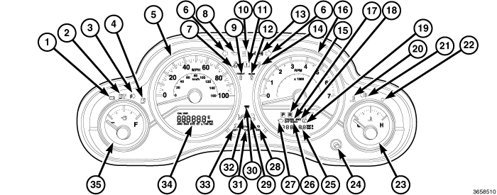 |
The instrument cluster assembly has provisions for up to 25 International Control and Display Symbol icon indicators and 4 analog gauges, (Refer to 08 - Electrical/8J - Instrument Cluster/GAUGE PACK, Instrument Cluster - Description) that are all controlled by the Cab Compartment Node (CCN) and standard on all models. Some of the indicators are automatically configured when the CCN is connected to the vehicle's electrical system for compatibility with certain optional equipment or equipment required for regulatory purposes in certain markets. While each instrument cluster may have provisions for indicators to support every available option, the configurable indicators will not function in vehicles that do not have the equipment that an indicator supports.
The instrument cluster includes provisions for the following indicators:
- Airbag Indicator (14)
- Ajar Indicators - text in odometer display (25) for doors and swing gate
- Antilock Brake System (ABS) Indicator (13)
- Brake Indicator (11) - text only for U.S. market, icon only for markets outside U.S.
- Change Oil Indicator - textual message in odometer display (25) on all domestic market vehicles and only certain export market vehicles equipped with a 2.8L diesel engine and an optional diesel particulate filter
- Charging Indicator (1)
- Cruise Indicator (17)
- Electronic Stability Program (ESP)/Brake Assist System (BAS) Indicator (33)
- Electronic Throttle Control (ETC) Indicator (32)
- Engine Coolant Temperature Indicator (20)
- Four-Wheel Drive (4WD) Indicator (18) - with optional four-wheel drive system only on domestic market vehicles. On export market vehicles, this indicator is located on the right side of the cluster overlay near the top, above the engine coolant temperature gauge.
- Four-Wheel Drive Lock (Off Road) Indicator (26) - Not Used
- Front Axle Lock Indicator (9) - with optional axle lockers only
- Front Fog Lamp Indicator (3) - with optional front fog lamps only
- Front Sway Bar Disconnect Indicator (31) - with optional electronic sway bar disconnect only
- Fuel Saver Indicator (ECO /ECO-on) (25) - textual message in Compass Mini-Trip Computer (CMTC) display.
- Gas Cap Indicator - textual message in odometer display (25)
- Gear Selector Indicator (15) - with automatic transmission only
- High Beam Indicator (10)
- Low Fuel Indicator (4)
- Low Oil Pressure Indicator (8)
- Malfunction Indicator Lamp (MIL) (27) - only on domestic market vehicles. On export market vehicles, this indicator is located on the right side of the cluster overlay near the top, above the engine coolant temperature gauge.
- No Bus Indicator - textual message in odometer display (25)
- No Fuse Indicator - textual message in odometer display (25)
- Overdrive Off Indicator (28) - with automatic transmission only
- Rear Axle Lock Indicator (12) - with optional axle lockers only
- Rear Fog Lamp Indicator (21) - in markets where rear fog lamps are available only
- Seat Belt Indicator (7)
- Security Indicator (22)
- Tire Pressure Monitor (TPM) Indicator (19)
- Traction Control/Electronic Stability Program (ESP) Indicator (29)
- Turn Signal (Right and Left) Indicators (6)
- Wait-To-Start Indicator (30) - with diesel engine only
- Water-In-Fuel Indicator (2) - with diesel engine only
The instrument cluster also includes the following Vacuum Florescent Display (VFD) units:
- Compass Mini-Trip Computer Display (34)
- Odometer Display (25) - includes Cruise indicator (17), Gear Selector indicator (15), Malfunction Indicator Lamp (MIL) (27) (domestic market vehicles only), Off Road indicator (26) (Not Used), Push Button (24), Tire Pressure Monitor (TPM) indicator (19) and 4WD indicator (18) (domestic market vehicles only).
For more information on the International Control and Display Symbol icons (Refer to 00 - Vehicle Data/Vehicle Information/International Vehicle Control and Display Symbols - Description) .
Each indicator in the instrument cluster, except those located within a VFD unit, is illuminated by a dedicated Light Emitting Diode (LED) that is soldered onto the CCN electronic circuit board. Cluster illumination is accomplished by several dimmable LED units, which illuminate each of the gauge dial faces for visibility when the exterior lighting is turned ON. These LED units as well as the CCN module are serviced only as a complete unit with the instrument cluster and, if damaged or ineffective, the entire instrument cluster assembly must be replaced. The cluster lens and the cluster hood and mask unit are the only components of the instrument cluster assembly that can be serviced separately.
OPERATION
The hard-wired indicator inputs may be diagnosed using conventional diagnostic tools and procedures. However, the CCN circuitry and electronic CAN or LIN data bus message controlled indicators are diagnosed using the self-diagnostic CCN Self test. (Refer to 08 - Electrical/8J - Instrument Cluster - Diagnosis and Testing) . For proper testing of the CAN or LIN data bus and the electronic data bus message inputs to the CCN that control each indicator requires the use of a diagnostic scan tool. Refer to the appropriate diagnostic information.
INDICATORS
Indicators are located in various positions within the instrument cluster and are all connected to the Cab Compartment Node (CCN) electronic circuit board. All the indicators are completely controlled by the CCN microprocessor. The various indicators are controlled by different strategies; some receive fused ignition switch output from the CCN circuitry and have a switched ground, while others are grounded through the CCN circuitry and have a switched battery feed. However, most are controlled by Controller Area Network (CAN) or Local Interface Network (LIN) data bus messages from other electronic modules in the vehicle but some are controlled by a combination of hard-wired inputs, electronic messaging and CCN programming. If the CCN loses CAN data bus communication, the CCN circuitry will automatically turn ON the Malfunction Indicator Lamp (MIL) until CAN data bus communication is restored.
The blue/green indicators located within the Vacuum Florescent Display (VFD) unit will dim accordingly with the instrument panel dimming. The red indicators within the VFD are at a fixed intensity. The cruise and 4WD indicators located within the odometer VFD unit are dimmable. All other indicators are illuminated at a fixed intensity, which is not affected by the selected illumination intensity of the instrument cluster general illumination Light Emitting Diode (LED) units. The illumination intensity of the dimmable indicators is synchronized with that of the general illumination lighting.
In addition, certain indicators in this instrument cluster are automatically or self-configured. This feature allows the configurable indicators to be enabled by the CCN circuitry for compatibility with certain optional equipment. These indicators are enabled or disabled by an electronic configuration message sent to the CCN by the Totally Integrated Power Module (TIPM). The TIPM defaults for the Anti-lock Brake System (ABS), and the airbag indicator's are enabled, and these configuration settings must be programmatically disabled in the TIPM using a diagnostic scan tool for vehicles that do not have this equipment. The automatically or self-configured indicators remain latent in each CCN at all times and will be active only when the CCN receives the appropriate CAN or LIN bus message inputs for that optional system or equipment.
Below are brief explanations of the indicators available on this vehicle. More detailed information may be available elsewhere in this manual under the module or system sections that control or influence the illumination of an indicator located within the instrument cluster or the VFD display's. For information on diagnosis and testing of the indicators (Refer to 08 - Electrical/8J - Instrument Cluster - Diagnosis and Testing) . The indicators, VFD displays as well as the gauges are only serviceable with the instrument cluster as an assembly. The cluster lens and hood and mask assembly are the only components serviceable separate of the instrument cluster.
ABS INDICATOR
The ABS indicator gives an indication to the vehicle operator when the ABS system is faulty or inoperative. This indicator is controlled by a low side driver on the CCN circuit board based upon programming and electronic messages received by the CCN from the Controller Antilock Brake (CAB) over the Controller Area Network (CAN) data bus. The CCN will illuminate the ABS indicator for about three seconds each time the ignition is turned to the ON position, during the bulb test.
The ABS indicator Light Emitting Diode (LED) is completely controlled by the CCN logic circuit, and that logic will only allow this indicator to operate when the instrument cluster receives a battery current input on the fused ignition switch output (run-start) circuit. Therefore, the LED will always be off when the ignition switch is in any position except ON or START. The LED only illuminates when it is provided a path to ground by the CCN transistor. The CCN will also illuminate the ABS indicator for the following reasons:
- ABS Lamp-ON Message - Each time the CCN a lamp-on message from the CAB, the ABS indicator will be illuminated. The indicator remains illuminated until the CCN receives a lamp-off message from the CAB, or until the ignition switch is turned to the OFF position, whichever occurs first.
- Communication Error - If the CCN receives no lamp-on or lamp-off messages from the CAB for five consecutive message cycles, the ABS indicator is illuminated. The indicator remains illuminated until a valid message from the CAB is received, or until the ignition switch is turned to the OFF position, whichever occurs first.
- ABS Diagnostic Test - The ABS indicator is blinked on and off by lamp-on and lamp-off messages from the CAB during the performance of the ABS diagnostic tests.
The CAB continually monitors the ABS circuits and sensors to decide whether the system is in good operating condition. The CAB then sends the proper lamp-on or lamp-off messages to the CCN. If the CAB sends a lamp-on message after the bulb test, it indicates that the CAB has detected a system malfunction and/or that the ABS system has become inoperative. The CAB will store a Diagnostic Trouble Code (DTC) for any malfunction it detects. Each time the ABS indicator fails to light due to an open or short in the cluster ABS indicator circuit, the cluster sends a message notifying the CAB of the condition, then the instrument cluster and the CAB will each store a DTC.
AIRBAG INDICATOR
The airbag indicator gives an indication to the vehicle operator when the airbag system is faulty or inoperative. The airbag indicator is controlled by a transistor on the CCN circuit board based upon programming and electronic messages received from the Occupant Restraint Controller (ORC) over the CAN data bus. Based on messages received from the ORC, the CCN will illuminate the airbag indicator for about six seconds each time the ignition is turned to the ON position, during the bulb test.
The airbag indicator LED is completely controlled by the CCN logic circuit, and that logic will only allow this indicator to operate when the instrument cluster receives a battery current input on the fused ignition switch output (run-start) circuit. Therefore, the LED will always be off when the ignition switch is in any position except ON or START. The LED only illuminates when it is provided a path to ground by the CCN transistor. The CCN will also illuminate the airbag indicator for the following reasons:
- ORC Lamp-ON Message - Each time the CCN receives a lamp-on message from the ORC, the airbag indicator will be illuminated. The indicator remains illuminated for about twelve seconds or until a lamp-off message from the ORC is received, whichever is longer.
- Communication Error - If the CCN receives no airbag messages for ten consecutive message cycles, the airbag indicator is illuminated. The indicator remains illuminated until the CCN receives a single lamp-off message from the ORC.
The ORC continually monitors the airbag system circuits and sensors to decide whether the system is in good operating condition. The ORC then sends the proper lamp-on or lamp-off messages to the CCN. If the ORC sends a lamp-on message after the bulb test, it indicates that the ORC has detected a system malfunction and/or that the airbags and seat belt tensioners may not deploy when required, or may deploy when not required. The ORC will store a DTC for any malfunction it detects. Each time the airbag indicator fails to illuminate due to an open or short in the CCN airbag indicator circuit, the CCN sends a message notifying the ORC of the condition, the CCN and the ORC will each store a DTC, and the seat belt indicator will flash on and off as a backup to notify the vehicle operator.
AXLE LOCK INDICATORS
The axle lock indicators gives an indication to the vehicle operator when the locking mechanism in the front or rear axles, if equipped with the optional off-road package are engaged. This indicator is controlled by a transistor on the CCN circuit board based upon programming and electronic messages received from the Totally Integrated Power Module (TIPM) over the CAN data bus
The front axle lock indicator LED is completely controlled by the CCN logic circuit, and that logic will only allow this indicator to operate when the instrument cluster receives a battery current input on the fused ignition switch output (run-start) circuit. Therefore, the LED will always be OFF when the ignition switch is in any position except ON or START. The LED only illuminates when it is provided a path to ground by the instrument cluster transistor. The CCN will illuminate either the front axle or rear lock indicators for the following reasons:
- Front Axle Lock Indicator Lamp-ON Message - Each time the cluster receives an electronic front axle lock lamp-ON message from the TIPM, the indicator will be illuminated. The indicator remains illuminated until the cluster receives a lamp-OFF message from the TIPM, or until the ignition switch is turned to the OFF position, whichever occurs first.
- Rear Axle Lock Indicator Lamp-ON Message - Each time the cluster receives an electronic rear axle lock lamp-ON message from the TIPM, the indicator will be illuminated. The indicator remains illuminated until the cluster receives a lamp-OFF message from the TIPM, or until the ignition switch is turned to the OFF position, whichever occurs first.
The TIPM continually monitors an input from the front axle lock solenoid to determine the status of the front axle lock mechanism. The TIPM then sends the proper lamp-ON or lamp-OFF message to the CCN.
BRAKE/PARK BRAKE INDICATOR
The brake indicator gives an indication to the vehicle operator when the parking brake is applied, when there are certain brake hydraulic system malfunctions as indicated by a low brake hydraulic fluid level condition, or when the brake fluid level switch is disconnected. The brake indicator can also give an indication when certain faults are detected in the ABS. This indicator is controlled by a transistor on the CCN circuit board based upon programming, electronic messages received from the CAB over the CAN data bus, and a hard-wired input from the park brake switch. The CCN will illuminate the brake indicator for about three seconds each time the ignition is turned to the ON position, during the bulb test.
The brake indicator LED is completely controlled by the CCN logic circuit, and that logic will only allow this indicator to operate when the instrument cluster receives a battery current input on the fused ignition switch output (run-start) circuit. Therefore, the LED will always be off when the ignition switch is in any position except ON or START. The LED only illuminates when it is provided a path to ground by the CCN transistor. The CCN will also illuminate the brake indicator for the following reasons:
- Brake Lamp-ON Message - Each time the CCN receives a lamp-on message from the CAB, the brake indicator will be illuminated. The CAB can also send brake lamp-on messages as feedback during ABS diagnostic procedures. The indicator remains illuminated until the a lamp-off message from the CAB is received, or until the ignition switch is turned to the OFF position, whichever occurs first.
- Park Brake Switch Input - Each time the CCN detects ground on the park brake switch sense circuit (park brake switch closed = park brake applied or not fully released) while the ignition switch is in the ON position, and vehicle speed in 8km (4.9 mph) or greater, the brake indicator flashes on and off. The indicator continues to flash until the park brake switch sense input to the CCN is an open circuit (park brake switch open = park brake fully released), or until the ignition switch is turned to the OFF position, whichever occurs first.
The park brake switch on the park brake pedal mechanism provides a hard-wired ground input to the CCN circuitry through the park brake switch sense circuit whenever the park brake is applied or not fully released. The CAB continually monitors the ABS system circuits and sensors, including the brake fluid level switch on the brake master cylinder reservoir, to decide whether the system is in good operating condition. The CAB then sends the proper lamp-on or lamp-off messages to the CCN. If the CAB sends a lamp-on message after the bulb test, it indicates that the CAB has detected a brake hydraulic system malfunction and/or that the ABS system has become inoperative. The CAB will store a DTC for any malfunction it detects.
CHANGE OIL INDICATOR
The change oil indicator gives an indication to the vehicle operator when a duty-cycle algorithm contained within the software of the Powertrain Control Module (PCM) determines that a recommended oil change interval has been attained. This indicator is controlled by the CCN logic circuit based upon programming and electronic messages received from the PCM over the CAN data bus.
The change oil indicator function of the VFD is completely controlled by the CCN logic circuit, and that logic will only allow this indicator to operate when the instrument cluster receives a battery current input on the fused ignition switch output (run-start) circuit. Therefore, the VFD change oil indication will always be OFF when the ignition switch is in any position except ON or START. The CCN will illuminate the change oil indicator for the following reasons:
- Change Oil Indicator Lamp-ON Message - Each time the ignition switch is turned to the ON position and the CCN receives an electronic change oil indicator lamp-ON message from the PCM indicating that a duty-cycle based recommended oil change interval has been attained, the change oil indicator will be illuminated for about three seconds, until the trip odometer reset switch button is depressed, or until the ignition switch is turned to the OFF position, whichever occurs first.
- Change Oil Indicator Reset Procedure - Once an engine oil change has been completed, the PCM duty cycle counters can be reset using the following procedure. Turn the ignition switch to the ON position, but DO NOT start the engine. Slowly depress and release the accelerator pedal fully three times within ten seconds. Turn the ignition switch to the OFF position. If the change oil indicator illuminates the next time the engine is started, repeat this procedure.
The PCM continually monitors numerous sensor inputs to determine the duty-cycles to which the engine is being subjected. A pre-programmed algorithm within the PCM then determines when to send the proper lamp-ON or lamp-OFF message to the CCN.
CHARGING INDICATOR
The charging indicator gives an indication to the vehicle operator when the electrical system voltage is too low or too high. This indicator is controlled by a transistor on the CCN circuit board based upon programming and electronic messages received Powertrain Control Module (PCM) over the CAN data bus. The CCN will illuminate the charge indicator for about three seconds each time the ignition is turned to the ON position, during the bulb test.
The charging indicator LED is completely controlled by the CCN logic circuit, and that logic will only allow this indicator to operate when the instrument cluster receives a battery current input on the fused ignition switch output (run-start) circuit. Therefore, the LED will always be off when the ignition switch is in any position except ON or START. The LED only illuminates when it is provided a path to ground by the CCN transistor. The CCN will also turn on the charging indicator for the following reasons:
- Voltage Low Message - Each time the CCN receives a message from the PCM indicating the electrical system voltage is low (less than about 11.5 volts is a charge fail condition), the charging indicator will be illuminated. The indicator remains illuminated until a message from the PCM indicating the electrical system voltage is normal (greater than about 12.0 volts, but less than 16.0 volts) is received, or until the ignition switch is turned to the OFF position, whichever occurs first.
- Voltage High Message - Each time the CCN receives a message from the PCM indicating the electrical system voltage is high (greater than about 16.0 volts), the charging indicator will be illuminated. The indicator remains illuminated until a message from the PCM indicating the electrical system voltage is normal (less than about 15.5 volts, but greater than 11.5 volts) is received, or until the ignition switch is turned to the OFF position, whichever occurs first.
The PCM continually monitors the electrical system voltage to control the generator output. The PCM then sends the proper system voltage messages to the CCN. If the charging indicator is turned on due to a charge fail or voltage high condition, it may indicate that the charging system requires service.
CRUISE INDICATOR
The cruise indicator gives an indication to the vehicle operator when the speed control system is ON, regardless of whether the speed control is engaged. This indicator is controlled by the CCN circuit board based upon programming and electronic messages received from the PCM over the CAN data bus.
The cruise indicator is completely controlled by the CCN logic circuit, and that logic will only allow this indicator to operate when the instrument cluster receives a battery current input on the fused ignition switch output (run-start) circuit. Therefore, the indicator will always be OFF when the ignition switch is in any position except ON or START. The indicator only illuminates when it is energized by the instrument cluster logic circuit. The instrument cluster will illuminate the cruise indicator for the following reasons:
- Cruise Indicator Lamp-ON Message - Each time the CCN receives an electronic cruise indicator lamp-ON message from the PCM indicating the speed control system is On, the cruise indicator is illuminated. The indicator remains illuminated until the cluster receives a lamp-OFF message from the PCM, or until the ignition switch is turned to the OFF position, whichever occurs first.
The PCM continually monitors the speed control switches to determine the appropriate outputs to control the vehicle speed. The PCM then sends the proper lamp-ON or lamp-OFF message to the CCN.
DOOR AJAR INDICATOR
The ajar indicators give an indication to the vehicle operator that one or more of the passenger compartment doors or the swing gate may be open or not completely latched. These indicators are controlled by the CCN logic circuit based upon programming and electronic ajar switch status messages from the TIPM over the CAN data bus.
The ajar indicator function of the odometer VFD unit is completely controlled by the instrument cluster logic circuit, and that logic will only allow this indicator to operate when the instrument cluster receives a battery current input on the fused B(+) circuit. Therefore, the VFD ajar indications can occur regardless of the ignition switch position. The CCN will turn On the ajar indicator for the following reasons:
- Ajar Switch Message Input - Each time the CCN receives a door or swing gate ajar switch status message indicating that a door, the swing gate or any combination of these is open or not completely latched with the ignition switch in any position, the appropriate ajar textual message will be illuminated. If the cluster detects a vehicle speed input greater than zero (kilometers or miles-per-hour) while the ignition switch is in the ON or START positions, the ajar indication will be accompanied by a single chime tone. When the ignition switch is in any position except ON or START, any and all ajar indications will time out after about five minutes.
The TIPM continually monitors the door and swing gate ajar switches to determine the status of the doors and swing gate. The TIPM then sends the proper ajar switch status messages to the CCN. The door and swing gate ajar switches and their circuits may be diagnosed using conventional diagnostic tools and methods. Refer to the appropriate wiring information.
ELECTRONIC THROTTLE CONTROL INDICATOR
The Electronic Throttle Control (ETC) indicator gives an indication to the vehicle operator when the ETC system is faulty or inoperative. The ETC indicator is controlled by a transistor on the CCN circuit board based upon programming and electronic messages received from the PCM over the CAN data bus. The CCN will illuminate the ETC indicator for about fifteen seconds each time the ignition is turned to the ON position, during the bulb test.
The ETC indicator LED is completely controlled by the CCN logic circuit, and that logic will only allow this indicator to operate when the instrument cluster receives a battery current input on the fused ignition switch output (run-start) circuit. Therefore, the LED will always be off when the ignition switch is in any position except ON or START. The LED only illuminates when it is provided a path to ground by the CCN transistor. The CCN will also turn on the ETC indicator for the following reasons:
- ETC Lamp-ON Message - Each time the CCN receives a lamp-on message from the PCM, the ETC indicator will be illuminated. The indicator can be flashed on and off, or illuminated solid, as dictated by the PCM message. The indicator remains illuminated solid or continues to flash for about twelve seconds or until a lamp-off message from the PCM is received, whichever is longer. If the indicator is illuminated solid with the engine running the vehicle will usually remain drivable. If the indicator is flashing with the engine running the vehicle may require towing. A flashing indicator means the ETC system requires immediate service.
The PCM continually monitors the ETC system circuits and sensors to decide whether the system is in good operating condition. The PCM then sends the proper lamp-on or lamp-off messages to the CCN. If the PCM sends a lamp-on message after the bulb test, it indicates that the PCM has detected an ETC system malfunction and/or that the ETC system is inoperative. The PCM will store a DTC for any malfunction it detects. Each time the ETC indicator fails to illuminate due to an open or short in the CCN ETC indicator circuit, the CCN sends a message notifying the PCM of the condition and the CCN and the PCM will each store a DTC.
ENGINE TEMPERATURE INDICATOR
The engine temperature indicator gives an indication to the vehicle operator when the engine temperature gauge reading reflects a condition requiring immediate attention. This indicator is controlled by a transistor on the CCN circuit board based upon programming and electronic messages received from the PCM over the CAN data bus. The CCN will illuminate the engine temperature indicator for about three seconds each time the ignition is turned to the ON position, during the bulb test.
The engine temperature indicator LED is completely controlled by the CCN logic circuit, and that logic will only allow this indicator to operate when the instrument cluster receives a battery current input on the fused ignition switch output (run-start) circuit. Therefore, the LED will always be off when the ignition switch is in any position except ON or START. The LED only illuminates when it is provided a path to ground by the CCN transistor. The engine temperature indicator will also be turned on for the following reasons:
- Engine Temperature High Message - Each time the CCN receives a message from the PCM indicating the engine coolant temperature is above about 252° F (122° C), the engine temperature indicator will be illuminated and a single chime tone is sounded. The indicator remains illuminated until a message from the PCM indicating that the engine coolant temperature is below about 246° F (119° C) is received, or until the ignition switch is turned to the OFF position, whichever occurs first. The chime tone feature will only repeat during the same ignition cycle if the engine temperature indicator is cycled off and then on again by the appropriate engine temperature messages from the PCM.
The PCM continually monitors the engine coolant temperature sensor to determine the engine operating temperature. The PCM then sends the proper engine coolant temperature messages to the CCN. If the CCN turns on the engine temperature indicator due to a high engine temperature gauge reading, it may indicate that the engine or the engine cooling system requires service.
ESP/BAS INDICATOR
The ESP/BAS indicator gives an indication to the vehicle operator when the Electronic Stability Program (ESP)/Brake Assist System (BAS) has been activated. This indicator is controlled by a transistor on the CCN circuit board based upon programming and electronic messages received from the Controller Antilock Brake (CAB) and the All-Wheel Drive Control Module (AWDCM) over the CAN data bus. The CCN will illuminate the ESP/BAS indicator for about tfour seconds each time the ignition is turned to the ON position, during the bulb test.
The ESP/BAS indicator LED is completely controlled by the instrument cluster logic circuit, and that logic will only allow this indicator to operate when the instrument cluster receives a battery current input on the fused ignition switch output (run-start) circuit. Therefore, the LED will always be OFF when the ignition switch is in any position except ON or START. The LED only illuminates when it is provided a path to ground by the instrument cluster transistor. The CCN will illuminate the ESP/BAS indicator for the following reasons:
- ESP/BAS Indicator Lamp-ON Message - Each time the cluster receives an electronic ESP/BAS indicator lamp-ON message from the CAB indicating that the ESP/BAS system has been activated, the ESP/BAS indicator will be illuminated. The indicator remains illuminated until the cluster receives a lamp-OFF message from the CAB, or until the ignition switch is turned to the OFF position, whichever occurs first.
- ESP Full OFF Textual Message - Each time the cluster receives an electronic ESP Full OFF indicator lamp-ON message from the CAB indicating that the ESP/BAS system has been manually disabled, an ESP Full OFF textual message will appear within the cluster odometer display. The ESP Full OFF textual message remains displayed until the cluster receives a lamp-OFF message from the CAB, or until the ignition switch is turned to the OFF position, whichever occurs first.
- ESP Permanent Disable Textual Message - Each time the cluster receives an electronic ESP Perm anent Disable message from the CAB indicating that the ESP/BAS system has been permanently disabled, an ESP OFF textual message will appear within the cluster odometer display for about 10 seconds each time the ignition switch is turned to the ON position.
The CAB continually monitors the ESP/BAS circuits and sensors to decide whether the system is in good operating condition and the proper outputs to the components of the system. The CAB then sends the proper lamp-ON or lamp-OFF message to the CCN.
For proper diagnosis of the ESP/BAS system, the CAB, the AWDCM, the CCN the CAN data bus or the electronic communication related to the ESP/BAS indicator operation a diagnostic scan tool is required. Refer to the appropriate diagnostic information.
FOG LAMP INDICATOR
The fog lamp indicator gives an indication to the vehicle operator whenever the optional fog lamps are illuminated. This indicator is controlled by a transistor on the CCN circuit board based upon programming and electronic messages from the Total Integrated Power Module (TIPM) over the CAN data bus.
The fog lamp indicator LED is completely controlled by the CCN logic circuit, and that logic will allow this indicator to operate whenever the instrument cluster receives a battery current input on the fused B(+) circuit. Therefore, the LED can be illuminated regardless of the ignition switch position. The LED only illuminates when it is provided a path to ground by the CCN transistor. The CCN will turn on the fog lamp indicator for the following reasons:
- Fog Lamp-ON Message - Each time the CCN receives a fog lamp-on message from the TIPM indicating the fog lamp relay is energized, the fog lamp indicator will be illuminated. The indicator remains illuminated until the cluster receives a fog lamp-off message from the TIPM.
The CCN continually monitors a hard-wired input from the headlamp switch to determine the selected fog lamp switch status. The CCN then sends the proper fog lamp-on and lamp-off messages to the TIPM over the CAN data bus. The TIPM activates the fog lamp relay then sends the proper fog lamp indicator lamp-on and lamp-off messages to the CCN.
FUEL SAVER INDICATOR - ECONOMIZER (ECO / ECO-ON)
The ECO / ECO-on message will display in the odometer display. The message will appear whenever the vehicle is driven in a fuel efficient manner, if the feature is turned ON by pressing the odometer push-button and toggling through the menu.
This feature allows the vehicle operator to monitor when they are driving in a fuel efficient manner, and it can be used to modify driving habits in order to increase fuel economy.
4WD INDICATOR
The four-wheel drive indicator gives an indication to the vehicle operator when a four-wheel drive (4WD) mode of the transfer case is selected. This indicator is controlled either by the CCN circuit board (domestic market vehicles) or by a transistor on the circuit board (export market vehicles) based upon programming and electronic messages received from the TIPM over the CAN data bus.
The four-wheel drive indicator is completely controlled by the CCN logic circuit, and that logic will only allow this indicator to operate when the instrument cluster receives a battery current input on the fused ignition switch output (run-start) circuit. Therefore, the indicator will always be OFF when the ignition switch is in any position except ON or START. The indicator only illuminates when it is energized by the CCN logic circuit. The CCN will illuminate the four-wheel drive indicator for the following reasons:
- Four-Wheel Drive Indicator Lamp-ON Message - Each time the cluster receives an electronic four-wheel drive indicator lamp-ON message from the TIPM indicating that a four-wheel drive mode is selected, the four-wheel drive indicator is illuminated. The indicator remains illuminated until the cluster receives a lamp-OFF message from the TIPM, or until the ignition switch is turned to the OFF position, whichever occurs first.
The TIPM continually monitors inputs from the four-wheel drive switch to determine the status of the transfer case. The TIPM then sends the proper lamp-ON or lamp-OFF message to the CCN.
GAS CAP INDICATOR
The gas cap indicator gives an indication to the vehicle operator when there is a gross leak detected in the on-board fuel vapor recovery system. This indicator is controlled by the CCN logic circuit based upon programming and electronic messages received from the PCM over the CAN data bus.
The gas cap indicator function of the odometer VFD unit is completely controlled by the CCN logic circuit, and that logic will only allow this indicator to operate when the instrument cluster receives a battery current input on the fused ignition switch output (run-start) circuit. Therefore, the odometer VFD gas cap indication will always be OFF when the ignition switch is in any position except ON or START. The CCN will illuminate the gas cap indicator for the following reasons:
- Gas Cap Indicator Lamp-ON Message - Each time the CCN receives an electronic gas cap indicator lamp-ON message from the PCM indicating there is a gross leak in the vapor recovery system, the gas cap indicator will be illuminated. The indicator remains illuminated until the cluster receives a lamp-OFF message from the PCM, or until the ignition switch is turned to the OFF position, whichever occurs first.
The PCM continually monitors the on board vapor recovery system to determine whether there are air leaks in the system. The PCM then sends the proper lamp-ON or lamp-OFF message to the CCN. If the CCN illuminates the gas cap indicator due to a monitored gross leak in the vapor recovery system, it may indicate that the gas cap has been removed or is improperly installed.
HIGH BEAM INDICATOR
The high beam indicator gives an indication to the vehicle operator whenever the headlamp high beams are illuminated. The TIPM sends a data Bus message for high beam indicator illumination, in turn the CCN takes this data Bus message directive to turn on the indicator.
The high beam indicator LED is completely controlled by the CCN logic circuit, and that logic will allow this indicator to operate whenever the instrument cluster receives a battery current input on the fused B(+) circuit. Therefore, the LED can be illuminated regardless of the ignition switch position. The LED only illuminates when it is provided a path to ground by the CCN transistor. The CCN will turn on the high beam indicator for the following reasons:
- High Beam Headlamps-ON Input - Each time the CCN detects a high beam headlamps-on input from the headlamp beam select switch circuitry of the multi-function switch on the washer/beam select switch mux circuit, the headlamp high beams and the high beam indicator will be illuminated. The headlamp high beams and the high beam indicator remain illuminated until the CCN receives a high beam headlamps-off input from the multi-function switch, or until the exterior lamp load shedding (battery saver) timed interval expires, whichever occurs first.
The CCN continually monitors the headlamp switch and the multi-function switch to determine the proper headlamp low beam and high beam control. The CCN then sends the proper low beam and high beam lamp-on and lamp-off messages to the TIPM over the CAN data bus and turns the high beam indicator on or off accordingly.
LOW FUEL INDICATOR
The low fuel indicator gives an indication to the vehicle operator when the level of fuel in the fuel tank becomes low. This indicator is controlled by a transistor on the CCN circuit board based upon programming and electronic fuel level messages received from the TIPM over the CAN data bus. The CCN will illuminate the low fuel indicator for about three seconds each time the ignition is turned to the ON position, during the bulb test
The low fuel indicator LED is completely controlled by the CCN logic circuit, and that logic will only allow this indicator to operate when the instrument cluster receives a battery current input on the fused ignition switch output (run-start) circuit. Therefore, the LED will always be OFF when the ignition switch is in any position except ON or START. The LED only illuminates when it is provided a path to ground by the CCN transistor. The CCN will illuminate the low fuel indicator for the following reasons:
- Less Than 11 Percent Tank Full Message - The TIPM provides a constant current source to the fuel level sending unit and monitors a return input on a fuel level sense circuit. The resistance through the fuel level sending unit increases as the fuel level rises and decreases as the fuel level falls causing changes in the fuel level sense input voltage. The TIPM then sends the appropriate electronic fuel level messages to the cluster. Each time the fuel level messages to the cluster indicate the fuel tank is about 11 percent full or less for 10 consecutive seconds and the vehicle speed is zero, or for 60 consecutive seconds and the vehicle speed is greater than zero, the gauge needle is moved to the appropriate position on the gauge scale, the low fuel indicator is illuminated, and a single chime tone is sounded. The low fuel indicator remains illuminated until the fuel level messages indicate that the fuel tank is greater than about 14 percent full for 10 consecutive seconds and the vehicle speed is zero, or for 60 consecutive seconds and the vehicle speed is greater than zero, or until the ignition switch is turned to the OFF position, whichever occurs first. The chime tone feature will only repeat during the same ignition cycle if the low fuel indicator is cycled OFF and then ON again by the appropriate messages from the TIPM.
- Less Than Empty Stop Message - Each time the cluster receives a fuel level message indicating the fuel level in the fuel tank is less than the E (or Empty) gauge needle stop position for five consecutive seconds, the gauge needle is moved to the low end of the gauge scale and the low fuel indicator is illuminated immediately. This input would indicate that the fuel level sense input to the TIPM is a short circuit.
- More Than Full Stop Message - Each time the cluster receives a fuel level message indicating the fuel level in the fuel tank is more than the F (or Full) gauge needle stop position for five consecutive seconds, the gauge needle is moved to the low end of the gauge scale and the low fuel indicator is illuminated immediately. This input would indicate that the fuel level sense input to the TIPM is an open circuit.
The TIPM continually monitors the fuel tank sending unit to determine the level of fuel in the fuel tank. The TIPM then sends the proper electronic fuel level message to the CCN and other electronic modules in the vehicle over the CAN data bus. The TIPM will store a Diagnostic Trouble Code (DTC) for any fault detected in the fuel level sense circuit.
LOW OIL PRESSURE INDICATOR
The low oil pressure indicator gives an indication to the vehicle operator when the engine oil pressure reading reflects a condition requiring immediate attention. This indicator is controlled by a transistor on the CCN circuit board based upon programming and electronic messages received from the PCM over the CAN data bus.
The low oil pressure indicator LED is completely controlled by the instrument cluster logic circuit, and that logic will only allow this indicator to operate when the instrument cluster receives a battery current input on the fused ignition switch output (run-start) circuit. Therefore, the LED will always be off when the ignition switch is in any position except ON or START. The LED only illuminates when it is provided a path to ground by the CCN transistor. The CCN will turn on the low oil pressure indicator for the following reasons:
- Engine Oil Pressure Low Message - Each time the CCN receives a message from the PCM indicating the engine oil pressure is about 4 psi (27.5 kPa) or lower, the low oil pressure indicator will be illuminated. The indicator remains illuminated until the CCN receives a message from the PCM indicating that the engine oil pressure is above about 4 psi (27.5 kPa), or until the ignition switch is turned to the OFF position, whichever occurs first. The CCN will only turn the indicator on in response to an engine oil pressure low message if the engine speed is greater than zero.
The PCM continually monitors the engine oil pressure sensor to determine the engine oil pressure. The PCM then sends the proper engine oil pressure messages to the CCN.
LOW TIRE PRESSURE INDICATOR
The Tire Pressure Monitor (TPM) indicator gives an indication to the vehicle operator of the status of the TPM system. The TPM indicator is controlled by the CCN circuit board based upon programming and electronic messages received from the Wireless Control Module (WCM) over the CAN data bus. The CCN will illuminate the TPM indicator for about three seconds each time the ignition is turned to the ON position, during the bulb test
The TPM indicator is completely controlled by the CCN's instrument cluster logic circuit, that logic only allow's this indicator to operate when the CCN receives a battery current input on the fused ignition switch output (run-start) circuit. Therefore, the indicator will always be OFF when the ignition switch is in any position except ON or START. The indicator only illuminates when it is energized by the instrument cluster logic circuit. The CCN will illuminate the TPM indicator for the following reasons:
- TPM Indicator Lamp-ON Message - Each time the CCN receives an electronic TPM indicator lamp-ON message from the WCM, the indicator will be illuminated. The indicator can be flashed ON and OFF, or illuminated solid, as dictated by the WCM message. The indicator remains illuminated until the cluster receives a lamp-OFF message, or until the ignition switch is turned to the OFF position, whichever occurs first.
- Low Tire Textual Message - ON vehicles manufactured for export markets, each time the CCN receives an electronic TPM indicator lamp-ON message from the WCM requesting the TPM indicator be illuminated solid, a LOtIRE textual message will appear within the odometer VFD display. The LOtIRE textual message remains displayed until the CCN receives a lamp-OFF message, or until the ignition switch is turned to the OFF position, whichever occurs first.
- Communication Error - If the CCN receives no TPM lamp-ON or lamp-OFF messages from the WCM for six consecutive seconds, the TPM indicator is illuminated. The indicator remains controlled and illuminated by the CCN until a valid lamp-ON or lamp-OFF message is received from the WCM.
MALFUNCTION INDICATOR LAMP
The Malfunction Indicator Lamp (MIL) gives an indication to the vehicle operator when the PCM has recorded a DTC for an ON-Board Diagnostics II (OBDII) emissions-related circuit or component malfunction. The MIL is controlled by a transistor on the CCN circuit board based upon programming and electronic messages received from the PCM over the CAN data bus. The CCN will illuminate the MIL indicator for about fifteen seconds each time the ignition is turned to the ON position, during the bulb test.
The MIL LED is completely controlled by the CCN logic circuit, and that logic will only allow this indicator to operate when the instrument cluster receives a battery current input on the fused ignition switch output (run-start) circuit. Therefore, the LED will always be off when the ignition switch is in any position except ON or START. The LED only illuminates when it is provided a path to ground by the CCN transistor. The CCN will also turn on the MIL for the following reasons:
- MIL Lamp-ON Message - Each time the CCN receives a MIL lamp-on message from the PCM, the indicator will be illuminated. The indicator can be flashed on and off, or illuminated solid, as dictated by the PCM message. For some DTC's, if a problem does not recur, the PCM will send a lamp-off message automatically. Other DTC's may require that a fault be repaired and the PCM be reset before a lamp-off message will be sent.
- Communication Error - If the CCN receives no messages from the PCM for ten consecutive message cycles, the MIL is illuminated by the CCN to indicate a loss of bus communication. The indicator remains illuminated until a valid message is received from the PCM.
The PCM continually monitors the fuel and emissions system circuits and sensors to decide whether the system is in good operating condition. The PCM then sends the proper lamp-on or lamp-off messages to the CCN. If the CCN turns on the MIL after the bulb test, it may indicate that a malfunction has occurred and that the fuel and emissions systems may require service.
OVERDRIVE OFF INDICATOR
The overdrive off indicator gives an indication to the vehicle operator when the electronically controlled overdrive feature of the automatic transmission has been disabled. This indicator is controlled by a transistor on the CCN circuit board based upon programming and electronic messages received from the PCM over the CAN data bus.
The overdrive off indicator LED is completely controlled by the CCN logic circuit, and that logic will only allow this indicator to operate when the instrument cluster receives a battery current input on the fused ignition switch output (run-start) circuit. Therefore, the LED will always be OFF when the ignition switch is in any position except ON or START. The LED only illuminates when it is provided a path to ground by the CCN transistor. The CCN will illuminate the overdrive off indicator for the following reasons:
- Overdrive OFF Indicator Lamp-ON Message - Each time the CCN receives an electronic overdrive off indicator lamp-ON message from the PCM indicating that the overdrive-OFF position of the tow/haul switch has been selected, the indicator will be illuminated. The indicator remains illuminated until the CCN receives a lamp-OFF message from the PCM, or until the ignition switch is turned to the OFF position, whichever occurs first.
The PCM continually monitors the overdrive switch to determine the proper outputs to the automatic transmission. The PCM then sends the proper lamp-ON or lamp-OFF message to the CCN.
REAR FOG LAMP INDICATOR
The rear fog lamp indicator gives an indication to the vehicle operator whenever the rear fog lamps are illuminated. This indicator is controlled by a transistor on the CCN circuit board based upon programming and electronic messages received from the TIPM over the CAN data bus.
The rear fog lamp indicator LED is completely controlled by the CCN logic circuit, and that logic will allow this indicator to operate whenever the instrument cluster receives a battery current input on the fused B(+) circuit. Therefore, the LED can be illuminated regardless of the ignition switch position. The LED only illuminates when it is provided a path to ground by the CCN transistor. The CCN will turn ON the rear fog lamp indicator for the following reasons:
- Rear Fog Indicator Lamp-ON Message - Each time the CCN receives an electronic rear fog indicator lamp-ON message from the TIPM indicating the rear fog lamps are turned ON, the rear fog lamp indicator will be illuminated. The indicator remains illuminated until the CCN receives a lamp-OFF message from the TIPM, or until the exterior lamp load shedding (battery saver) timed interval expires, whichever occurs first.
The TIPM continually monitors electronic exterior lighting request messages from the CCN to determine the appropriate outputs to the rear fog lamps. The TIPM activates or deactivates the rear fog lamps then sends the proper lamp-ON or lamp-OFF message back to the CCN.
SEAT BELT INDICATOR
The seat belt indicator gives an indication to the vehicle operator of the status of the driver side front seat belt. This indicator is controlled by a transistor on the CCN circuit board based upon cluster programming and a hard-wired input from the seat belt switch in the driver side front seat belt retractor through the seat belt indicator driver circuit.
The seat belt indicator also includes a programmable enhanced seat belt reminder or “beltminder” feature that is enabled when the vehicle is shipped from the factory. This beltminder feature can be disabled and enabled by the customer using a specific programming event sequence, or by the dealer using a diagnostic scan tool.
The seat belt indicator LED is completely controlled by the CCN logic circuit, and that logic will only allow this indicator to operate when the instrument cluster receives a battery current input on the fused ignition switch output (run-start) circuit. Therefore, the LED will always be off when the ignition switch is in any position except ON or START. The LED only illuminates when it is provided a path to ground by the CCN transistor. The CCN will turn on the seat belt indicator for the following reasons:
- Seat Belt Reminder Function - Each time the CCN receives a battery current input on the fused ignition switch output (run-start) circuit, the indicator will be illuminated as a seat belt reminder for about six seconds, or until the ignition switch is turned to the OFF position, whichever occurs first. This reminder function will occur regardless of the status of the seat belt switch input to the cluster.
- Driver Side Front Seat Belt Not Buckled - Beltminder Active - Following the seat belt reminder function, each time the CCN detects an open circuit on the seat belt indicator driver circuit (seat belt switch open = seat belt unbuckled) with the ignition switch in the START or ON positions, the indicator will be illuminated. In addition, if the driver side front seat belt remains unbuckled after the conclusion of the seat belt reminder function, with the vehicle speed greater than about5 MPH (8 Kph), the seat belt indicator will begin to cycle between flashing on and off for three seconds, then lighting solid for two seconds. The seat belt indicator will continue to cycle between flashing and solid illumination for thirteen complete cycles, until the seat belt indicator driver input to the cluster is closed to ground (seat belt switch closed = seat belt buckled), or until the ignition switch is turned to the OFF position, whichever occurs first.
- Driver Side Front Seat Belt Not Buckled - Beltminder Inactive - Following the seat belt reminder function, each time the cluster detects an open circuit on the seat belt indicator driver circuit (seat belt switch open = seat belt unbuckled) with the ignition switch in the START or ON positions, the indicator will be illuminated. The seat belt indicator remains illuminated until the seat belt indicator driver input to the cluster is closed to ground (seat belt switch closed = seat belt buckled), or until the ignition switch is turned to the OFF position, whichever occurs first.
The seat belt switch is connected in series between ground and the seat belt indicator driver input to the instrument cluster. The seat belt switch input to the instrument cluster circuitry may be diagnosed using conventional diagnostic tools and methods. Refer to the appropriate wiring information.
SECURITY INDICATOR
The security indicator gives an indication to the vehicle operator when the Vehicle Theft Security System (VTSS) is arming or is armed. ON models equipped with the Sentry Key Immobilizer System (SKIS), the security indicator also gives an indication to the vehicle operator of the status of the SKIS. This indicator is controlled by a transistor on the CCN circuit board based upon programming, hard-wired inputs to the CCN from the various security system components, electronic messages received from the WIN over the CAN data bus. The CCN will illuminate the security indicator for about three seconds each time the ignition is turned to the ON position, during the bulb test.
The security indicator LED is completely controlled by the CCN logic circuit, and that logic will allow this indicator to operate whenever the instrument cluster receives a battery current input on the fused B(+) circuit. Therefore, the LED can be illuminated regardless of the ignition switch position. The LED only illuminates when it is provided a path to ground by the CCN transistor. The CCN will also turn on the security indicator for the following reasons:
- VTSS Indication - During the sixteen second VTSS arming function, the cluster will flash the security indicator on and off repeatedly at a steady, fast rate to indicate that the VTSS is in the process of arming. Following successful VTSS arming, the cluster flashes the security indicator on and off continuously at a slower rate to indicate that the VTSS is armed. The security indicator continues flashing at the slower rate until the VTSS is disarmed or triggered. If the VTSS has alarmed and rearmed, the cluster will flash the security indicator at a steady, slow rate for about thirty seconds after the VTSS is disarmed.
- SKIS Lamp-ON Message - Each time the CCN receives a SKIS lamp-on message from the WIN, the security indicator will be illuminated. The indicator can be flashed on and off, or illuminated solid, as dictated by the WIN message. The indicator remains illuminated solid or continues to flash until the CCN receives a SKIS lamp-off message from the WIN, or until the ignition switch is turned to the OFF position, whichever occurs first. For more information on the SKIS and the security indicator control parameters, (Refer to 08 - Electrical/8Q - Vehicle Theft Security - Operation) .
- Communication Error - If the CCN receives no SKIS lamp-on or lamp-off messages from the WIN for ten consecutive message cycles, the security indicator is illuminated by the CCN. The indicator remains controlled and illuminated by the CCN until a valid SKIS lamp-on or lamp-off message is received.
The CCN circuitry controls the security indicator whenever the ignition switch is in the OFF position and the VTSS is arming, armed, or alarming. Whenever the ignition switch is in the ON or START positions, the WIN performs a self-test to decide whether the SKIS is in good operating condition and whether a valid key is present in the ignition lock cylinder. The WIN then sends the proper lamp-on or lamp-off messages to the CCN. If the instrument cluster flashes the security indicator upon ignition ON, or turns on the security indicator solid after the bulb test, it indicates that a SKIS malfunction has occurred or that the SKIS is inoperative.
SWAY BAR DISCONNECT INDICATOR
The front sway bar disconnect indicator gives an indication to the vehicle operator when the locking mechanism of the front sway bar of vehicles equipped with the optional off-road package is disengaged. This indicator is controlled by a transistor on the CCN circuit board based upon programming and electronic messages received from the TIPM over the CAN data bus
The front sway bar disconnect indicator LED is completely controlled by the CCN logic circuit, and that logic will only allow this indicator to operate when the instrument cluster receives a battery current input on the fused ignition switch output (run-start) circuit. Therefore, the LED will always be OFF when the ignition switch is in any position except ON or START. The LED only illuminates when it is provided a path to ground by the instrument cluster transistor. The CCN will illuminate the front sway bar disconnect indicator for the following reasons:
- Front Sway Bar Disconnect Indicator Lamp-ON Message - Each time the CCN receives an electronic front sway bar disconnect lamp-ON message from the TIPM, the indicator will be illuminated. The indicator remains illuminated until the cluster receives a lamp-OFF message from the TIPM, or until the ignition switch is turned to the OFF position, whichever occurs first.
The TIPM continually monitors an input from the front sway bar disconnect solenoid to determine the status of the front sway bar disconnect mechanism. The TIPM then sends the proper lamp-ON or lamp-OFF message to the CCN.
TRACTION CONTROL INDICATOR
The traction control indicator gives an indication to the vehicle operator when the electronic Traction Control System (TCS) has been activated. This indicator is controlled by the CCN circuit board based upon programming and electronic messages received from the CAB over the CAN data bus. The CCN will illuminate the traction control indicator for about four seconds each time the ignition is turned to the ON position, during the bulb test.
The traction control indicator is completely controlled by the instrument cluster logic circuit, and that logic will only allow this indicator to operate when the instrument cluster receives a battery current input on the fused ignition switch output (run-start) circuit. Therefore, the indicator will always be off when the ignition switch is in any position except ON or START. The indicator only illuminates when it is switched to ground by the instrument cluster circuitry. The instrument cluster will turn on the traction control indicator for the following reasons:
- Traction Control Lamp-ON Message - Each time the CCN receives a traction control lamp-ON message from the CAB indicating that the TCS has been activated, the traction control indicator will be illuminated. The indicator remains illuminated until a traction control lamp-off message from the CAB is received, or until the ignition switch is turned to the OFF position, whichever occurs first.
The CAB continually monitors the traction control switch to determine the proper outputs to the components of the ABS. The CAB then sends the proper traction control lamp-on and lamp-OFF messages to the CCN.
TRANSMISSION RANGE INDICATOR
The electronic gear selector indicator gives an indication to the vehicle operator of the transmission gear that has been selected with the automatic transmission gear selector lever. This indicator is controlled by the instrument cluster circuit board based upon cluster programming and electronic messages received from the Powertrain Control Module (PCM) over the Controller Area Network (CAN) data bus.
The gear selector indicator information is displayed by the odometer Vacuum Fluorescent Display (VFD) unit soldered onto the instrument cluster electronic circuit board, and the VFD will not display the gear selector indicator information after the ignition switch is turned to the OFF position. Each time the cluster is disconnected from battery current for more than about five minutes, it must configure itself for the automatic transmission type that is in the vehicle once it is reconnected to battery current. The instrument cluster circuitry operates the gear selector indicator to provide the following features:
- Selected Gear Message - Each time the cluster receives an electronic selected gear message from the PCM, a box will be illuminated around the appropriate character in the gear selector indicator. The box will remain illuminated until the cluster receives a different selected gear message, or until the ignition switch is turned to the OFF position, whichever occurs first.
- Communication Error - If the cluster fails to receive a selected gear message from the PCM within three seconds, the instrument cluster circuitry will display all gear selector positions boxed (selected) until a valid selected gear message is received or until the ignition switch is turned to the OFF position, whichever occurs first.
The PCM continually monitors a hard-wired multiplex input from the Transmission Range Sensor (TRS), then sends the proper message to the CCN.
TURN SIGNAL INDICATORS
The turn signal indicators give an indication to the vehicle operator that the turn signal (left or right indicator flashing) or hazard warning (both left and right indicators flashing) have been selected and are operating. These indicators are controlled by transistors on the CCN electronic circuit board based upon the cluster programming, a hard-wired multiplex input received by the cluster from the turn signal and hazard warning switch circuitry of the multi-function switch on the turn/hazard switch mux circuit, and electronic messages received from the TIPM over the CAN data bus.
Each turn signal indicator LED is completely controlled by the CCN logic circuit, and that logic will allow this indicator to operate whenever the instrument cluster receives a battery current input on the fused B(+) circuit. Therefore, each LED can be illuminated regardless of the ignition switch position. The LED only illuminates when it is provided a path to ground by the CCN transistor. The CCN will turn on the turn signal indicators for the following reasons:
- Turn Signal-ON Input - The Steering Control Module (SCM) sends a Data Bus message to the TIPM to turn on the turn signals. The TIPM also sends out a message to the CCN to illuminate the appropriate electronic turn signal switch indicator. The TIPM controls the output and the flash rate for either the right or left turn signal lamps and sends this message to the CCN. The CCN will then control the illumination and flash rate of the right or left turn signal indicators, as well as to control the click rate of an electromechanical relay soldered onto the CCN electronic circuit board that emulates the sound emitted by a conventional turn signal flasher. The turn signals and the turn signal indicators continue to flash on and off until the cluster receives a turn signal-off input from the multi-function switch, or until the ignition switch is turned to the OFF position, whichever occurs first.
- Hazard Warning-ON Input - The turn signal flashers are also controlled by the TIPM. The SCM sends a Data Bus message to the TIPM and the TIPM responds to these messages by controlling a battery voltage output and the flash rate for each of the right and left turn signal lamps. The TIPM also sends the appropriate electronic messages back to the CCN to control the illumination and flash rate of the right and left turn signal indicators, as well as to control the click rate of an electromechanical relay soldered onto the CCN electronic circuit board that emulates the sound emitted by a conventional hazard warning flasher. The turn signals and the turn signal indicators continue to flash on and off until the cluster receives a hazard warning-off input from the multi-function switch.
- Lamp Out Mode - The CCN also sends electronic turn signal on and off messages to the TIPM over the CAN data bus, and the TIPM flashes the appropriate exterior turn signal lamps. If the TIPM detects an inoperative turn signal lamp or circuit, it increases the flash rate for the remaining operative turn signals and sends an electronic message back to the instrument cluster. The instrument cluster then increases the flash rate of the turn signal indicator(s) and the clicking rate of the electromechanical relay to provide an indication of the problem to the vehicle operator.
The CCN continually monitors the multi-function switch and electronic messages from the TIPM to determine the proper turn signal and hazard warning system control.
WAIT-TO-START INDICATOR
The wait-to-start indicator gives an indication to the vehicle operator when the diesel engine is too cool for efficient and reliable engine starting, and the engine glow plugs are energized in their pre-heat operating mode. This indicator is controlled by a transistor on the CCN circuit board based upon programming and electronic messages received from the PCM over the CAN data bus.
The wait-to-start indicator LED is completely controlled by the CCN logic circuit, and that logic will only allow this indicator to operate when the instrument cluster receives a battery current input on the fused ignition switch output (run-start) circuit. Therefore, the LED will always be OFF when the ignition switch is in any position except ON or START. The LED only illuminates when it is provided a path to ground by the CCN transistor. The CCN will illuminate the wait-to-start indicator for the following reasons:
- Wait-To-START Indicator Lamp-ON Message - Each time the CCN receives an electronic wait-to-start indicator lamp-ON message from the PCM indicating that the air temperature is too cool for efficient and reliable engine starting and the glow plugs are energized in their pre-heat mode, the wait-to-start indicator will be illuminated. The indicator remains illuminated until the cluster receives a lamp-OFF message from the PCM, until the PCM detects that the engine is running, or until the ignition switch is turned to the OFF position, whichever occurs first.
The PCM continually monitors the glow plug control circuits to determine when they are energized in their pre-heat operating mode. The PCM then sends the proper lamp-ON or lamp-OFF message to the CCN.
WATER IN FUEL INDICATOR
The water-in-fuel indicator gives an indication to the vehicle operator when there is excessive water detected in the diesel fuel. This indicator is controlled by the CCN based upon programming and electronic messages received from the PCM over the CAN data bus.
The water-in-fuel indicator LED is completely controlled by the cluster logic circuit, and that logic will only allow this indicator to operate when the instrument cluster receives a battery current input on the fused ignition switch output (run-start) circuit. Therefore, the LED will always be OFF when the ignition switch is in any position except ON or START. The LED only illuminates when it is provided a path to ground by the CCN transistor. The CCN will illuminate the water-in-fuel indicator for the following reasons:
- Water-In-Fuel Indicator Lamp-ON Message - Each time the CCN receives an electronic water-in-fuel indicator lamp-ON message from the PCM indicating there is excessive water in the diesel fuel system, the water-in-fuel indicator will be illuminated. The indicator remains illuminated until the cluster receives a lamp-OFF message from the PCM, or until the ignition switch is turned to the OFF position, whichever occurs first.
The PCM continually monitors the water-in-fuel sensor to determine whether there is excessive water in the diesel fuel system. The PCM then sends the proper electronic water-in-fuel message to the CCN.