ANTENNA, Navigation
DESCRIPTION
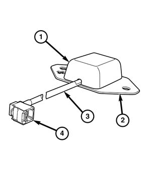 |
In vehicles equipped with the navigation system and the optional satellite audio feature the navigation antenna has been integrated into the satellite antenna on the roof of the vehicle. (Refer to 08 - Electrical/8A - Audio and Video/ANTENNA, Satellite/Operation) . In vehicles equipped with the navigation system, but not equipped with the optional satellite audio feature, a dedicated navigation antenna module (1) is used.
The dedicated navigation antenna module is located near the top of the instrument panel base trim, concealed behind the instrument panel center bezel. The navigation antenna module has a stamped metal mounting flange (2) that is secured to the instrument panel base trim by two push-in plastic fasteners. A single pigtail cable (3) with an integral connector (4) exits the antenna module and is routed through the instrument panel to the navigation unit (also known as the Telematics Gateway Module/TGW), which is integral to the Radio Receiver Module (RRM) (also known as the radio or the head unit).
The dedicated navigation antenna module cannot be adjusted or repaired.
If damaged or ineffective the entire unit must be replaced.
OPERATION
The navigation module acquires Global Positioning System (GPS) position data through a navigation antenna module. Vehicles equipped with the optional satellite radio system have a roof-mounted combination antenna that also receives satellite audio and cellular signals. (Refer to 08 - Electrical/8A - Audio and Video/ANTENNA, Satellite/Operation) . Vehicles not equipped with the optional satellite radio system have a dedicated navigation antenna module mounted near the top of the instrument panel below the windshield.
The navigation antenna module is used to provide satellite information for route calculation and vehicle positioning purposes to the navigation unit (also known as the Telematics Gateway Module/TGW), which is integral to the Radio Receiver Module (RRM) (also known as the radio or the head unit). The antenna modules receive time pulse information from the GPS satellites, then calculate and transmit altitude, latitude, longitude, number of satellites, satellite direction, satellite angle of elevation, direction, signal to noise ratio and accuracy information.
The hard wired circuits between components related to the navigation antenna module may be diagnosed using conventional diagnostic tools and procedures. Refer to the appropriate wiring information. The wiring information includes wiring diagrams, proper wire and connector repair procedures, details of wire harness routing and retention, connector pin out information and location views for the various wire harness connectors, splices and grounds.
However, conventional diagnostic methods will not prove conclusive in the diagnosis of the navigation antenna module or the electronic controls and communication between modules and other devices that provide some features of the navigation system. The most reliable, efficient and accurate means to diagnose the navigation antenna module or the electronic controls and communication related to navigation system operation requires the use of a diagnostic scan tool. Refer to the appropriate diagnostic information.
DIAGNOSIS AND TESTING - NAVIGATION ANTENNA
The hard wired circuits between components related to the navigation antenna module may be diagnosed using conventional diagnostic tools and procedures. Refer to the appropriate wiring information. The wiring information includes wiring diagrams, proper wire and connector repair procedures, details of wire harness routing and retention, connector pin out information and location views for the various wire harness connectors, splices and grounds.
However, conventional diagnostic methods will not prove conclusive in the diagnosis of the navigation antenna module or the electronic controls and communication between modules and other devices that provide some features of the navigation system. The most reliable, efficient and accurate means to diagnose the navigation antenna module or the electronic controls and communication related to navigation system operation requires the use of a diagnostic scan tool. Refer to the appropriate diagnostic information.
REMOVAL
To avoid serious or fatal injury
on vehicles equipped with airbags, disable the Supplemental Restraint
System (SRS) before attempting any steering wheel, steering column,
airbag, seat belt tensioner, impact sensor or instrument panel component
diagnosis or service. Disconnect and isolate the battery negative
(ground) cable, then wait two minutes for the system capacitor to
discharge before performing further diagnosis or service. This is
the only sure way to disable the SRS. Failure to take the proper precautions
could result in accidental airbag deployment.
WARNING:
 |
In vehicles equipped with the optional satellite radio system, the navigation antenna is serviced as a unit with the combination antenna located on the roof panel. (Refer to 08 - Electrical/8A - Audio and Video/ANTENNA, Satellite/Removal) .
- Disconnect and isolate the negative cable from the battery.
- Remove the center bezel from the instrument panel. (Refer to 23 - Body/Instrument Panel/BEZEL, Instrument Panel, Lower/Removal) .
- Remove the Radio Receiver Module (RRM) (also known as the radio or the head unit) from the instrument panel. (Refer to 08 - Electrical/8A - Audio and Video/RADIO - Removal) .
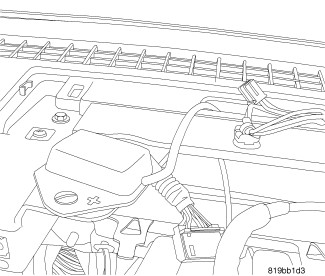
- Remove the two plastic push-in fasteners that secure the Global Positioning System (GPS) antenna to the instrument panel base trim.
-
Remove the GPS antenna
from the instrument panel.
INSTALLATION
To avoid serious or fatal injury
on vehicles equipped with airbags, disable the Supplemental Restraint
System (SRS) before attempting any steering wheel, steering column,
airbag, seat belt tensioner, impact sensor or instrument panel component
diagnosis or service. Disconnect and isolate the battery negative
(ground) cable, then wait two minutes for the system capacitor to
discharge before performing further diagnosis or service. This is
the only sure way to disable the SRS. Failure to take the proper precautions
could result in accidental airbag deployment.
WARNING:
|
In vehicles equipped with the optional satellite radio system, the navigation antenna is serviced as a unit with the combination antenna located on the roof panel. (Refer to 08 - Electrical/8A - Audio and Video/ANTENNA, Satellite/Removal) .
- Position the Global Positioning System (GPS) antenna to the instrument panel base trim.
- Reinstall the two plastic push-in fasteners that secure the GPS antenna to the instrument panel base trim.
- Reinstall the Radio Receiver Module (RRM) (also known as the radio or the head unit) into the instrument panel. (Refer to 08 - Electrical/8A - Audio and Video/RADIO - Installation) .
- Reinstall the center bezel onto the instrument panel. (Refer to 23 - Body/Instrument Panel/BEZEL, Instrument Panel, Lower/Installation) .
-
Reconnect the negative
cable to the battery.