COOLER and HOSES, Charge Air
REMOVAL
 |
If the engine was just turned off,
the air intake system tubes may be hot.
WARNING:
| NOTE: |
When servicing the Air Charge Cooler and/or Turbocharger, the Air Charger Hose (orange) seal located between the Air Charge Hose and Turbocharger must be replaced. |
| NOTE: |
Note the location of the rubber charge air cooler to A/C condenser and air charger cooler to radiator air seals. The seals are use to prevent overheating and improve charge air and A/C efficiency. |
Review the warnings and cautions
for this system before performing the procedure. Failure to follow
these instructions may result in serious injury or death.
WARNING:
- Disconnect the battery negative cable.
- Raise and support the vehicle.
- Remove the wheelhouse splash shield, (Refer to 23 - Body/Exterior/SHIELD, Splash - Removal) .
- Remove the lower radiator seal push pins.
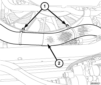
- Remove the lower radiator hose to fan shroud retainers (1).
- Remove the lower electric cooling fan mounting bolts.
- Drain the coolant from the radiator, (Refer to 07 - Cooling - Standard Procedure) .
- Remove the lower radiator hose (2).
-
Lower the vehicle.
- Remove the grille, (Refer to 23 - Body/Exterior/GRILLE - Removal) .
- Recover the refrigerant from the refrigerant system (Refer to 24 - Heating and Air Conditioning/Plumbing - Standard Procedure) .
- Remove the air filter housing assembly, (Refer to 09 - Engine/Air Intake System/BODY, Air Cleaner - Removal) .
- Remove the viscous fan, cooling fan and fan shroud as an assembly, (Refer to 07 - Cooling/Engine/FAN, Cooling - Removal) .
- Remove the upper radiator hose.
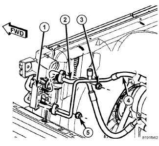
- Remove the nuts (3 and 5) that secure the A/C discharge line (2) and A/C liquid line (4) to the A/C condenser (1).
- Disconnect the A/C discharge and liquid lines from the A/C condenser and remove and discard the O-ring seals and gaskets.
-
Install plugs into,
or tape over the opened refrigerant line fittings and condenser ports.
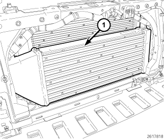
- Remove the hoses from the charge air cooler (1).
-
Remove the radiator
mounting bolts.
NOTE: Care must be taken not to damage the charge air cooler fins and the fins of other ancillary cooler components.
- Remove the radiator, A/C condenser and charge air cooler as an assembly.
-
Remove the charge air
cooler to condenser bolts and separate the charge air cooler (1).
INSTALLATION
|
| NOTE: |
When servicing the Air Charge Cooler and/or Turbocharger, the Air Charger Hose (orange) seal located between the Air Charge Hose and Turbocharger must be replaced. |
-
Install the charge
air cooler to the A/C condenser/radiator assembly. Tighten the bolts
to 10 N·m (89 in. lbs.).
NOTE: Care must be taken not to damage the charge air cooler fins and the fins of other ancillary cooler components.
- Position the radiator, A/C condenser and charge air cooler into the vehicle as an assembly.
- Install the radiator mounting bolts. Tighten the bolts to 9 N·m (81 in. lbs.).
-
Install the hoses to
the charge air cooler (1). Tighten the clamps to 11 N·m (95 in. lbs.).
- Remove the tape or plugs from the opened refrigerant line fittings and condenser ports.
- Lubricate a new rubber O-ring seals with clean refrigerant oil and install them and new gaskets onto the refrigerant line fittings. Use only the specified O-ring seals as they are made of a special material for the R-134a system. Use only refrigerant oil of the type recommended for the A/C compressor in the vehicle.
- Connect the A/C discharge line (2) and the A/C liquid line (4) to the A/C condenser (1). Install the retaining nuts (3 and 5). Tighten the nuts to 23 N·m (17 ft. lbs.).
- Install the upper radiator hose.
- Install the viscous fan, cooling fan and fan shroud as an assembly (Refer to 07 - Cooling/Engine/FAN, Cooling - Installation) .
- Install the air filter housing assembly (Refer to 09 - Engine/Air Intake System/BODY, Air Cleaner - Installation) .
- Charge the refrigerant system (Refer to 24 - Heating and Air Conditioning/Plumbing - Standard Procedure) .
-
Install the grille, (Refer to 23 - Body/Exterior/GRILLE
- Installation)
.
- Raise and support the vehicle (Refer to 04 - Vehicle Quick Reference/Hoisting/Standard Procedure) .
- Install the lower radiator hose (2).
- Install the lower electric cooling fan bolts. Tighten the bolts to 6 N·m (53 in. lbs.).
- Install the lower radiator hose to fan shroud retainers (1).
- Install the lower radiator seal push pins.
- Install the wheelhouse splash shield, (Refer to 23 - Body/Exterior/SHIELD, Splash - Installation)
- Lower the vehicle.
- Fill the cooling system, (Refer to 07 - Cooling - Standard Procedure) .
- Connect the battery negative cable.
-
Start engine and check
for leaks.