Multi-display Communication Error
Circuit diagnosis
INSPECTION PROCEDURE
| 1. IDENTIFY THE COMPONENT SHOWN BY SUB-CODE |

Enter the diagnostic mode.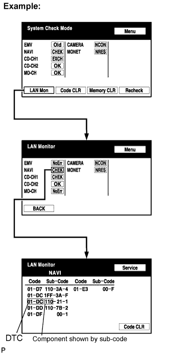

Press the "LAN Mon" switch to change to "LAN Monitor" mode.
Identify the component shown by the sub-code.
- HINT:
- "110 (multi-display)" is the component shown by the sub-code in the example shown in the illustration.
- The sub-code will be indicated by its physical address.
- For the component list, refer to "DIAGNOSIS DISPLAY DETAILED DESCRIPTION" (Click here).
- "110 (multi-display)" is the component shown by the sub-code in the example shown in the illustration.
| NEXT | |
 |
| 2. CHECK POWER SOURCE CIRCUIT OF COMPONENT SHOWN BY SUB-CODE |
Inspect the power source circuit of the component shown by the sub-code.If the power source circuit is operating normally, proceed to the next step.
Component Table: Component
Proceed to
Radio receiver (190)
Radio receiver power source circuit (Click here)
Stereo component amplifier (440)
Stereo component amplifier power source circuit (Click here)
Gateway ECU (1C6)
Gateway ECU power source circuit (Click here)
Navigation ECU (178)
Navigation ECU power source circuit (Click here)
Television camera ECU (1AC)
Television camera ECU power source circuit (Click here)
| NEXT | |
|
| 3. INSPECT RADIO RECEIVER |
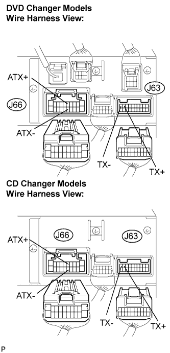 |
Disconnect the radio receiver connectors.
Measure the resistance according to the value(s) in the table below.
- Standard resistance:
Tester Connection
Condition
Specified Condition
ATX+ (J66-5) -
ATX- (J66-15)
Always
60 to 80 Ω
TX+ (J63-9) -
TX- (J63-10)
Always
60 to 80 Ω
|
|
||||

| OK | |
|
| 4. CHECK HARNESS AND CONNECTOR (MULTI-DISPLAY - COMPONENT SHOWN BY SUB-CODE) |
- HINT:
- Start the check from the circuit that is near the component shown by the sub-code first.
- For details of the connectors, refer to "TERMINALS OF ECU" (Click here).
- Start the check from the circuit that is near the component shown by the sub-code first.
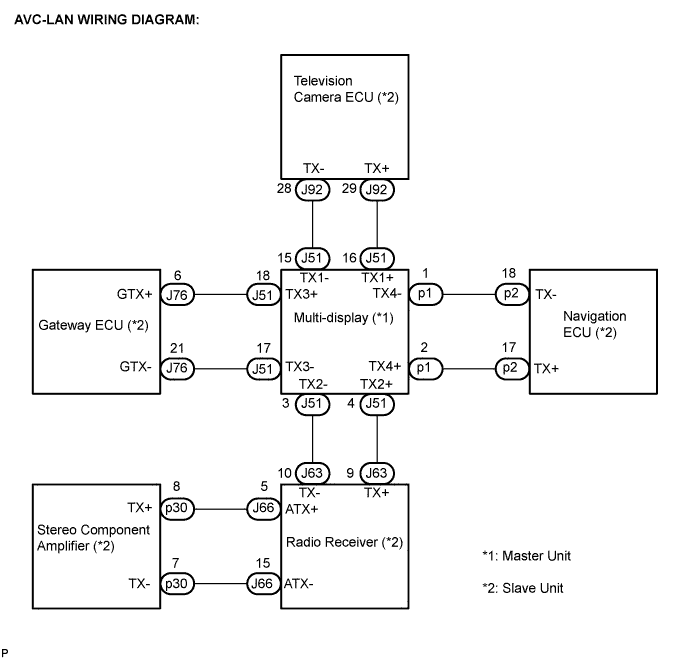
Referring to the AVC-LAN wiring diagram below, check the AVC-LAN circuit between the multi-display and the component shown by the sub-code.
Disconnect all connectors between the multi-display and the component shown by sub-code.
Check for an open or short in the AVC-LAN circuit between the multi-display and the component shown by the sub-code.
- OK:
- There is no open or short circuit.
|
|
||||
| OK | |
|
| 5. REPLACE COMPONENT SHOWN BY SUB-CODE |
Replace the component shown by the sub-code with a normal one and check if the same problem occurs again.
- OK:
- Same problem does not occur.
|
|
||||
| OK | ||
 |
||
| ||