| Last Modified: 11-27-2007 | 1.6 J | |
| Service Category: Audio/Visual/Telematics | Section: Audio/Video | |
| Model Year: 2008 | Model: LX570 | Doc ID: RM000002LS6004X |
| Title: AUDIO / VIDEO: REAR SEAT ENTERTAINMENT SYSTEM: INSPECTION PROCEDURE (2008 LX570) | ||
|
Black Screen |
INSPECTION PROCEDURE
PROCEDURE
|
1. |
CHECK TELEVISION DISPLAY ASSEMBLY (POWER) |
(a) Check if the power of the television display is on.
OK:
Power is on.
|

|
2. |
CHECK TELEVISION DISPLAY ASSEMBLY (OPENING ANGLE) |
|
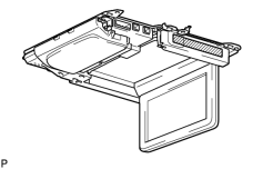
(a) Check if the television display is open 90° or more. OK: Open 90° or more. HINT:
The television display tilt can be adjusted to 4 positions: 90°, 100°, 110° and 120°. |
|
|
3. |
CHECK MODE IN WHICH BLACK SCREEN OCCURRED |
(a) Check the mode in which the black screen occurred.
Result
|
Result |
Proceed to |
|---|---|
|
During navigation image, screen turned black |
A |
|
During DVD image, screen turned black |
B |
|
During VTR image, screen turned black |
C |
|
|
4. |
CHECK DISPLAY SIGNAL CIRCUIT BETWEEN MULTI-DISPLAY AND TELEVISION DISPLAY ASSEMBLY |
(a) Refer to the Display Signal Circuit between Multi-display and Television Display
 . If the display signal circuit is operating normally, proceed to the next step.
|
|
5. |
CHECK AVC-LAN CIRCUIT |
(a) Refer to the AVC-LAN Circuit
. If the AVC-LAN circuit is operating normally, proceed to the next step.
|
|
6. |
CHECK HARNESS AND CONNECTOR (TELEVISION DISPLAY ASSEMBLY - BODY GROUND) |
|
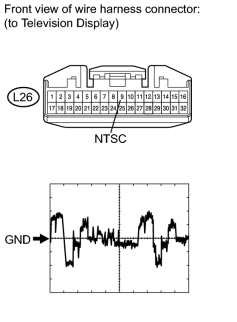
(a) Disconnect the L26 display connector. |
(b) Check the waveform of the television display using an oscilloscope.
Measurement Condition
|
Item |
Content |
|---|---|
|
Terminal No. (Symbol) |
L26-9 (NTSC) - Body ground |
|
Tool Setting |
200 mV/DIV., 10 μsec./DIV. |
|
Condition |
DVD displayed on television display |
OK:
Waveform is as shown in the illustration.
|
|
7. |
DISPLAY SIGNAL CIRCUIT BETWEEN RADIO RECEIVER AND TELEVISION DISPLAY ASSEMBLY |
(a) Refer to the Display Signal Circuit between Radio Receiver and Television Display
. If the display signal circuit is operating normally, proceed to the next step.
|
|
8. |
CHECK AVC-LAN CIRCUIT |
(a) Refer to the AVC-LAN Circuit
. If the AVC-LAN circuit is operating normally, proceed to the next step.
|
|
9. |
CHECK HARNESS AND CONNECTOR (TELEVISION DISPLAY ASSEMBLY - BODY GROUND) |
|
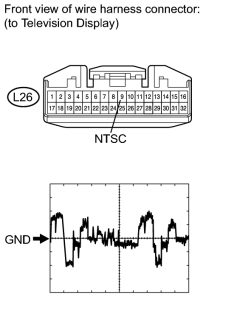
(a) Disconnect the L26 display connector. |
(b) Check the waveform of the television display using an oscilloscope.
Measurement Condition
|
Item |
Content |
|---|---|
|
Terminal No. (Symbol) |
L26-9 (NTSC) - Body ground |
|
Tool Setting |
200 mV/DIV., 10 μsec./DIV. |
|
Condition |
DVD displayed on television display |
OK:
Waveform is as shown in the illustration.
|
|
10. |
CHECK DISPLAY SIGNAL CIRCUIT BETWEEN VIDEO TERMINAL AND TELEVISION DISPLAY |
(a) Refer to the Display Signal Circuit between Video Terminal and Television Display
. If the display signal circuit is operating normally, proceed to the next step.
|
|
11. |
CHECK AVC-LAN CIRCUIT |
(a) Refer to the AVC-LAN Circuit
. If the AVC-LAN circuit is operating normally, proceed to the next step.
|

|

|