| Last Modified: 11-27-2007 | 1.6 A | |
| Service Category: Vehicle Exterior | Section: Door/Hatch | |
| Model Year: 2008 | Model: LX570 | Doc ID: RM000002M8100CX |
| Title: DOOR / HATCH: REAR DOOR: DISASSEMBLY (2008 LX570) | ||
DISASSEMBLY
HINT:
- Use the same procedures for the RH side and LH side.
- The procedures listed below are for the LH side.
1. REMOVE ENGINE ROOM SIDE COVER LH

2. DISCONNECT CABLE FROM NEGATIVE BATTERY TERMINAL
NOTICE:
-
w/ Navigation System:
After the engine switch is turned off, the HDD navigation system requires approximately 6 minutes to record various types of memory and settings. As a result, after turning the engine switch off, wait 6 minutes or more before disconnecting the cable from the negative (-) battery terminal.
-
When disconnecting the cable, some systems need to be initialized after the cable is reconnected
.
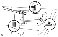
3. REMOVE REAR DOOR INSIDE HANDLE BEZEL PLUG LH
|
(a) Using a screwdriver, detach the 3 claws and remove the inside handle bezel plug. HINT:
Tape the screwdriver tip before use. |
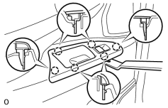
4. REMOVE REAR UPPER DOOR ARMREST BASE PANEL LH
|
(a) Using a moulding remover, detach the 6 claws. |
(b) Disconnect the connector and remove the rear upper door armrest base panel and rear power window regulator switch assembly.
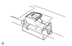
5. REMOVE REAR POWER WINDOW REGULATOR SWITCH ASSEMBLY
|
(a) Detach the 2 claws and remove the regulator switch. |
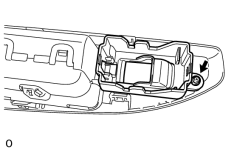
6. REMOVE REAR LOWER DOOR ARMREST BASE PANEL LH
|
(a) Remove the screw and rear lower door armrest base panel. |
7. REMOVE REAR DOOR TRIM BOARD SUB-ASSEMBLY LH
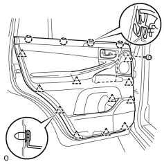
|
(a) Remove the 2 screws. |
(b) Detach the 11 clips and 4 claws.
(c) Disconnect the connector and remove the trim board.
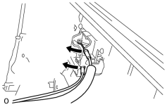
|
(d) Disconnect the 2 cables from the inside handle. |
8. REMOVE REAR DOOR INSIDE HANDLE ILLUMINATION LIGHT ASSEMBLY LH
9. REMOVE REAR NO. 2 SPEAKER ASSEMBLY (for 19 Speakers)
10. REMOVE REAR NO. 3 SPEAKER ASSEMBLY (for 19 Speakers)
11. REMOVE REAR DOOR INSIDE HANDLE SUB-ASSEMBLY LH
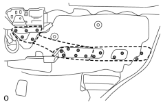
|
(a) Remove the 17 screws and rear door armrest assembly LH. |
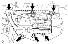
|
(b) Remove the 6 screws and inside handle. |
12. REMOVE COURTESY LIGHT ASSEMBLY
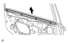
13. REMOVE REAR INNER DOOR GLASS WEATHERSTRIP LH
|
(a) Remove the weatherstrip by pulling it upward in the direction indicated by the arrow in the illustration. |
14. REMOVE REAR SPEAKER SET
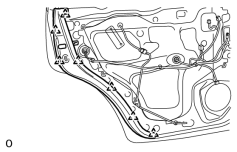
15. REMOVE REAR DOOR TRIM COVER LH
|
(a) Detach the 7 clips and remove the door trim cover. |
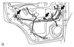
16. REMOVE REAR DOOR SERVICE HOLE COVER LH
|
(a) Using a clip remover, detach the 6 clamps. |
(b) Remove the bolt and disconnect the 2 connectors.
(c) Remove the service hole cover.
HINT:
Remove the remaining tape on the door.
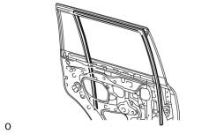
17. REMOVE REAR DOOR GLASS RUN LH
|
(a) Remove the rear door glass run from the window frame. |
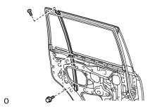
18. REMOVE REAR DOOR REAR LOWER WINDOW FRAME SUB-ASSEMBLY LH
|
(a) Remove the 2 bolts. |
(b) Remove the screw and window frame.
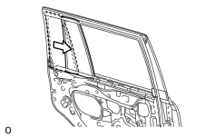
19. REMOVE REAR DOOR QUARTER WINDOW GLASS LH
|
(a) Remove the rear door quarter window glass and rear door quarter window weatherstrip as a unit as shown in the illustration. |
20. REMOVE REAR DOOR QUARTER WINDOW WEATHERSTRIP LH
(a) Remove the quarter window weatherstrip.
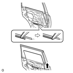
21. REMOVE REAR DOOR GLASS SUB-ASSEMBLY LH
|
(a) Remove the rear door glass sub-assembly from the rear door window regulator sub-assembly as shown in the illustration. NOTICE:
Do not damage the door glass. |
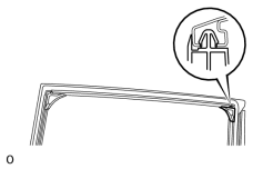
22. REMOVE REAR DOOR FRAME GARNISH LH
|
(a) Detach the clip and remove the rear door frame garnish. HINT:
The rear door frame garnish needs to be replaced with a new one because the clip will break when removing the rear door frame garnish. |
23. REMOVE REAR NO. 2 DOOR FRAME GARNISH LH
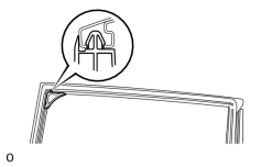
|
(a) Detach the clip and remove the rear door frame garnish. HINT:
The rear door frame garnish needs to be replaced with a new one because the clip will break when removing the rear door frame garnish. |
24. REMOVE REAR DOOR WINDOW REGULATOR SUB-ASSEMBLY LH
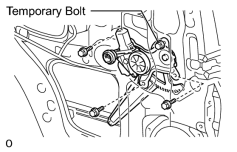
|
(a) Loosen the temporary bolt. NOTICE:
Do not remove the temporary bolt. If the temporary bolt is removed, the rear door window regulator may fall and become damaged. |
(b) Remove the 3 bolts and regulator.
NOTICE:
Be careful when removing the bolts as the regulator may fall and become damaged.
(c) Remove the temporary bolt from the rear door window regulator sub-assembly.
25. REMOVE REAR NO. 1 POWER WINDOW REGULATOR MOTOR ASSEMBLY LH
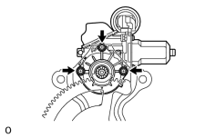
|
(a) Using a T25 "TORX" driver, remove the 3 screws and motor. NOTICE:
Be careful when removing the screws as the motor may fall and become damaged. |
26. REMOVE REAR NO. 3 DOOR WEATHERSTRIP LH
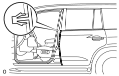
|
(a) Detach the claw and remove the rear No. 3 door weatherstrip. |
27. REMOVE REAR DOOR BELT MOULDING ASSEMBLY LH
28. REMOVE REAR DOOR FRONT WINDOW FRAME MOULDING LH
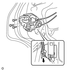
29. REMOVE REAR DOOR LOCK ASSEMBLY LH
|
(a) Disconnect the connector. |
(b) Using a T30 "TORX" socket, remove the 3 screws and door lock.
NOTICE:
Be careful when removing the screws as the door lock may fall and become damaged.
HINT:
Remove the door lock through the service hole.
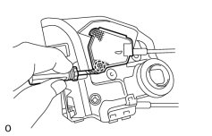
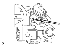
30. REMOVE REAR DOOR LOCK REMOTE CONTROL CABLE ASSEMBLY LH
|
(a) Using a screwdriver, detach the claw. HINT:
Tape the screwdriver tip before use. |
|
(b) Remove the rear door lock remote control cable. |
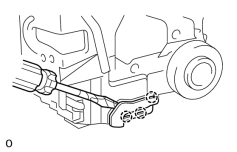
31. REMOVE REAR DOOR INSIDE LOCKING CABLE ASSEMBLY LH
|
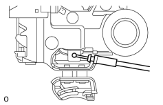
(a) Using a screwdriver, detach the 3 claws. HINT:
Tape the screwdriver tip before use. |
|
(b) Remove the rear door inside locking cable. |
32. REMOVE REAR DOOR OUTSIDE HANDLE COVER LH
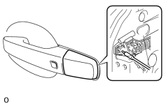
|
(a) Using a T30 "TORX" socket, loosen the screw. |
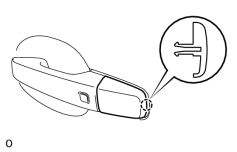
|
(b) Detach the claw and remove the rear door outside handle cover. |
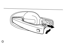
33. REMOVE REAR DOOR OUTSIDE HANDLE ASSEMBLY LH
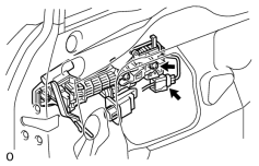
|
(a) Using a T30 "TORX" wrench, loosen the screw. |
|
(b) Disconnect the connector. |
(c) Remove the handle by sliding and pulling it in the direction indicated by the arrow in the illustration.
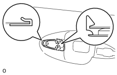
34. REMOVE REAR NO. 1 DOOR OUTSIDE HANDLE PAD LH
|
(a) Detach the 3 claws and remove the pad. |
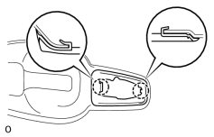
35. REMOVE REAR NO. 2 DOOR OUTSIDE HANDLE PAD LH
|
(a) Detach the 2 claws and remove the pad. |
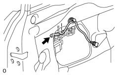
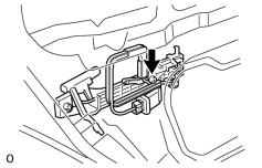
36. REMOVE REAR DOOR OUTSIDE HANDLE FRAME SUB-ASSEMBLY LH
|
(a) Detach the clamp. |
|
(b) Using a T30 "TORX" socket, loosen the screw. |
(c) Slide the outside handle frame and No. 4 electrical key wire harness to remove them.
HINT:
Remove the outside handle frame through the service hole.
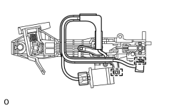
37. REMOVE NO. 4 ELECTRICAL KEY WIRE HARNESS
|
(a) Disconnect the connector. |
(b) Detach the 2 clamps, and remove the wire harness from the frame.
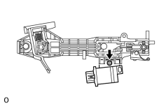
38. REMOVE DOOR ELECTRICAL KEY OSCILLATOR
|
(a) Remove the screw and door electrical key oscillator. |
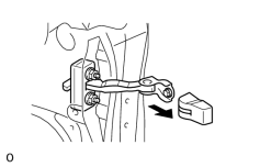
39. REMOVE REAR DOOR CHECK COVER LH
|
(a) Remove the cover. |
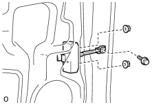
40. REMOVE REAR DOOR CHECK ASSEMBLY LH
|
(a) Remove the bolt, 2 nuts and door check. HINT:
Remove the door check through the service hole. NOTICE:
Be careful when removing the bolt and nuts as the door check may fall and become damaged. |
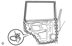
41. REMOVE REAR DOOR WEATHERSTRIP LH
|
(a) Detach the 21 clips and remove the rear door weatherstrip. HINT:
If clips are damaged during removal, replace them. |

|

|