| Last Modified: 11-27-2007 | 1.6 A | |
| Service Category: Vehicle Interior | Section: Interior Panels/Trim | |
| Model Year: 2008 | Model: LX570 | Doc ID: RM0000038MM003X |
| Title: INTERIOR PANELS / TRIM: ROOF HEADLINING: INSTALLATION (2008 LX570) | ||
INSTALLATION
HINT:
A bolt without a torque specification is shown in the standard bolt chart
 .
.
1. INSTALL NO. 2 MULTIPLEX NETWORK BODY ECU
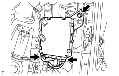
(a) Install the multiplex network body ECU with the bolt.
(b) Connect the 2 connectors.
2. INSTALL SIDE TRIM BOX (w/o Woofer)
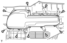
(a) Install the side trim box with the 9 screws.
3. INSTALL SIDE TRIM BOX COVER (w/o Woofer)
(a) Install the side trim box cover.
4. INSTALL QUARTER TRIM LID SUB-ASSEMBLY RH
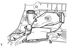
(a) Install the quarter trim lid.
5. INSTALL QUARTER TRIM COVER LH (for Rear No. 2 Seat with Automatic Folding-up Function)
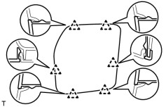
(a) Attach the 6 clips to install the quarter trim cover.
6. INSTALL FOLD SEAT SWITCH ASSEMBLY (for Rear No. 2 Seat with Automatic Folding-up Function)
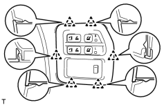
(a) Attach the 6 clips to install the fold seat switch.
7. INSTALL REAR NO. 2 SEAT COVER BEZEL (for Rear No. 2 Seat with Manual Folding-up Function)
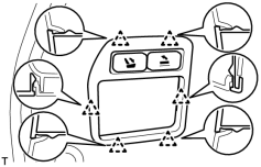
(a) Attach the 6 clips to install the No. 2 seat cover bezel.
8. INSTALL REAR NO. 1 SEAT COVER BEZEL (for Rear No. 2 Seat with Manual Folding-up Function)
HINT:
Use the same procedures described for the LH side.
9. INSTALL REAR SEAT LOCK CONTROL LEVER SUB-ASSEMBLY LH (for Rear No. 2 Seat with Manual Folding-up Function)
10. INSTALL REAR SEAT LOCK CONTROL LEVER SUB-ASSEMBLY RH (for Rear No. 2 Seat with Manual Folding-up Function)
HINT:
Use the same procedures described for the LH side.
11. INSTALL NO. 2 SIDE TRIM BASE COVER LH
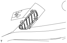
(a) Attach the 4 claws to install the cover.
12. INSTALL NO. 2 SIDE TRIM BASE COVER RH
HINT:
Use the same procedures described for the LH side.
13. INSTALL NO. 1 SIDE TRIM BASE COVER LH
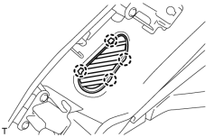
(a) Attach the 4 claws to install the cover.
14. INSTALL NO. 1 SIDE TRIM BASE COVER RH
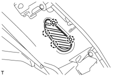
(a) Attach the 4 claws to install the cover.
|
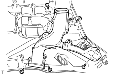
(b) Install the duct with the 6 screws. |
15. INSTALL NO. 2 CUP HOLDER
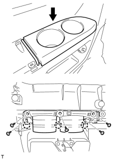
(a) Attach the 3 claws to install the cup holder.
(b) Install the 5 screws.
16. INSTALL NO. 1 CUP HOLDER
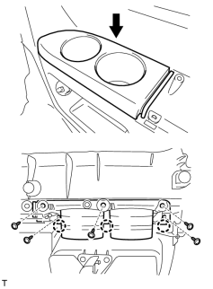
(a) Attach the 3 claws to install the cup holder.
(b) Install the 5 screws.
17. INSTALL QUARTER TRIM COVER SUB-ASSEMBLY LH
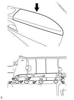
(a) Attach the 4 claws to install the quarter trim cover.
(b) Install the 7 screws.
|
(c) Install the duct with the 8 screws. |
18. INSTALL QUARTER TRIM COVER SUB-ASSEMBLY RH
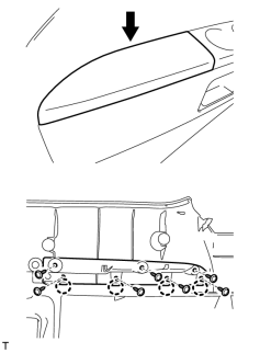
(a) Attach the 4 claws to install the quarter trim cover.
(b) Install the 7 screws.
19. INSTALL REAR NO. 2 SEAT SHOULDER BELT HANGER LH
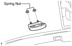
(a) Install the hanger with new 2 spring nuts.
20. INSTALL REAR NO. 2 SEAT SHOULDER BELT HANGER RH
HINT:
Use the same procedures described for the LH side.
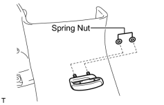
21. INSTALL REAR NO. 1 SEAT SHOULDER BELT HANGER
HINT:
Use the same procedure to install the hanger on the other side.
(a) Install the hanger with new 2 spring nuts.
22. INSTALL ROOF SIDE INNER GARNISH COVER LH

(a) Attach the 7 claws to install the cover.
23. INSTALL ROOF SIDE INNER GARNISH COVER RH
HINT:
Use the same procedures described for the LH side.
24. INSTALL REAR SHOULDER BELT ANCHOR PLATE SUB-ASSEMBLY LH
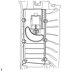
(a) Attach the 6 claws to install the plate.
25. INSTALL REAR SHOULDER BELT ANCHOR PLATE SUB-ASSEMBLY RH
HINT:
Use the same procedures described for the LH side.
26. INSTALL FRONT SHOULDER BELT ANCHOR PLATE SUB-ASSEMBLY LH
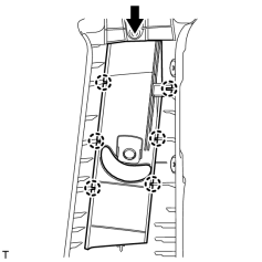
(a) Slide the plate in the direction shown in the illustration and attach the 6 claws to install the plate.
27. INSTALL FRONT SHOULDER BELT ANCHOR PLATE SUB-ASSEMBLY RH
HINT:
Use the same procedures described for the LH side.
28. INSTALL REAR DOOR SCUFF PLATE OUTSIDE LH
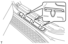
(a) Attach the 3 clips to install the rear door scuff plate outside.
29. INSTALL REAR DOOR SCUFF PLATE OUTSIDE RH
HINT:
Use the same procedures described for the LH side.
30. INSTALL FRONT DOOR SCUFF PLATE OUTSIDE LH
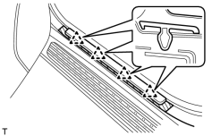
(a) Attach the 4 clips to install the front door scuff plate outside.
31. INSTALL FRONT DOOR SCUFF PLATE OUTSIDE RH
HINT:
Use the same procedures described for the LH side.
32. INSTALL BACK DOOR WEATHERSTRIP
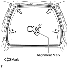
(a) Install the back door weatherstrip as shown in the illustration.
33. INSTALL REAR DOOR OPENING TRIM WEATHERSTRIP LH
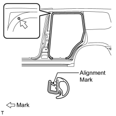
(a) Install the rear door opening trim weatherstrip as shown in the illustration.
34. INSTALL REAR DOOR OPENING TRIM WEATHERSTRIP RH
HINT:
Use the same procedures described for the LH side.
35. INSTALL FRONT DOOR OPENING TRIM WEATHERSTRIP LH
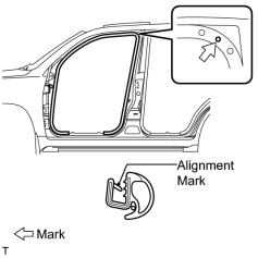
(a) Install the front door opening trim weatherstrip as shown in the illustration.
36. INSTALL FRONT DOOR OPENING TRIM WEATHERSTRIP RH
HINT:
Use the same procedures described for the LH side.
37. INSTALL ROOF HEADLINING ASSEMBLY
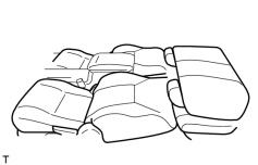
HINT:
- When installing the roof headlining, connect the cable to the negative (-) battery terminal and move the front seats and No. 1 rear seat to the position shown in the illustration.
- After moving the seats, disconnect the cable from the negative (-) battery terminal.
|
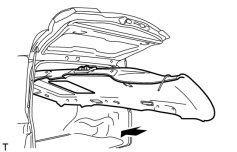
(a) Place the headlining in the cabin from the rear of the vehicle as shown in the illustration. NOTICE:
Be careful not to damage the roof headlining when placing it in the cabin. |
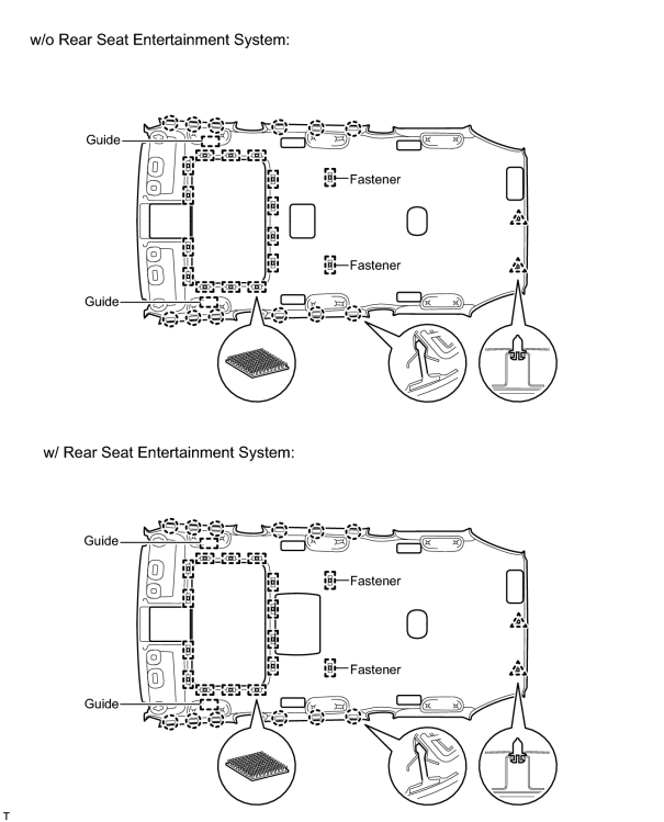
(b) Attach the 2 guides, 12 claws, 2 clips and 16 fasteners to install the headlining.
|
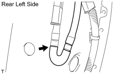
(c) Connect the washer hose. |
|
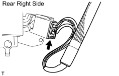
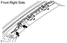
(d) Connect the antenna cord connector. |
|
(e) Connect the antenna cord connector and attach the 2 clamps. |
(f) Install the bolt.
|
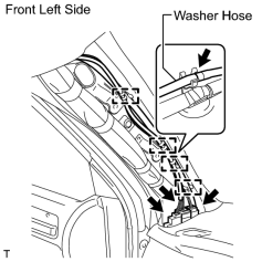
(g) Connect the 3 roof wire connectors and washer hose. |
(h) Attach the 4 clamps.
|
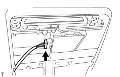
(i) Connect the drive gear connector. |
|
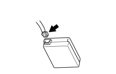
(j) Connect the rain sensor connector. |
|
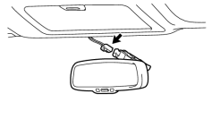
(k) Connect the inner mirror connector. |
38. INSTALL FRONT ROOF SIDE RAIL GARNISH LH
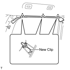
(a) Install 3 new clips to the roof side rail garnish.
(b) Attach the 3 clips to install the roof side rail garnish.
39. INSTALL FRONT ROOF SIDE RAIL GARNISH RH
HINT:
Use the same procedures described for the LH side.
40. INSTALL 3RD SEAT ASSIST GRIP ASSEMBLY
HINT:
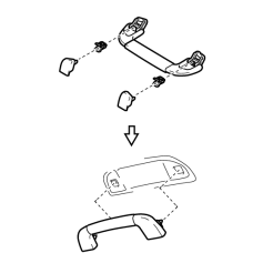
Use the same procedure to install the 3rd seat assist grip on the other side.
(a) Assemble the assist grip, 2 clips and 2 covers as shown in the illustration.
(b) Install the assist grip.
41. INSTALL NO. 2 ASSIST GRIP ASSEMBLY LH
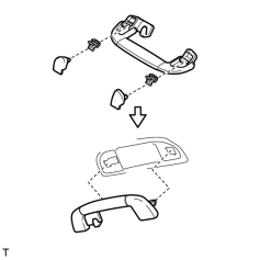
(a) Assemble the assist grip, 2 clips and 2 covers as shown in the illustration.
(b) Install the assist grip.
42. INSTALL NO. 2 ASSIST GRIP ASSEMBLY RH
HINT:
Use the same procedures described for the LH side.
43. INSTALL ASSIST GRIP ASSEMBLY
HINT:
Use the same procedure to install the assist grip on the other side.
(a) Assemble the assist grip, 2 clips and 2 covers as shown in the illustration.
(b) Install the assist grip.
44. INSTALL SEAT BELT ANCHOR COVER
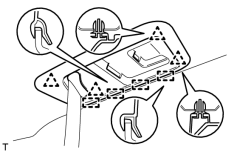
(a) Attach the 4 guides and 4 clips to install the seat belt anchor cover.
45. INSTALL RAIN SENSOR COVER
46. INSTALL INNER REAR VIEW MIRROR STAY HOLDER COVER
47. INSTALL CENTER VISOR ASSEMBLY LH
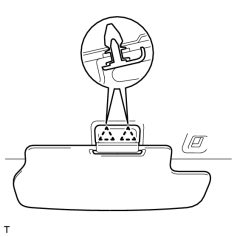
(a) Attach the 2 clips to install the center visor.
48. INSTALL CENTER VISOR ASSEMBLY RH
HINT:
Use the same procedures described for the LH side.
49. INSTALL VISOR HOLDER
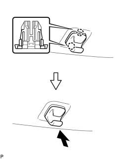
HINT:
Use the same procedures to install the visor holder on the other side.
(a) Attach the 2 claws.
(b) Push in the visor holder to install it.
50. INSTALL VISOR ASSEMBLY LH
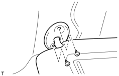
(a) Install the visor with the 2 screws.
51. INSTALL VISOR ASSEMBLY RH
HINT:
Use the same procedures described for the LH side.
52. INSTALL VISOR BRACKET COVER
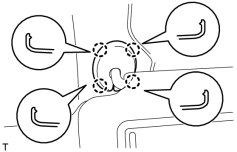
HINT:
Use the same procedure to install the visor bracket cover on the other side.
(a) Attach the 4 claws to install the visor bracket cover.
53. INSTALL NO. 3 ROOM LIGHT ASSEMBLY
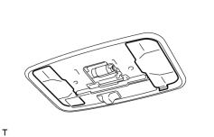
(a) Install the 2 covers.
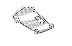
|
(b) Attach the 4 claws to install the room light lens. |
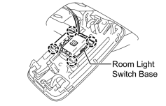
|
(c) Attach the 4 claws to install the room light to the room light switch base. |
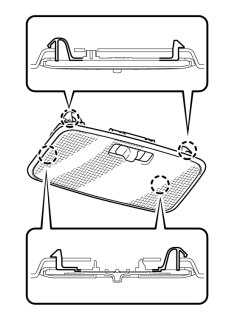
|
(d) Attach the 4 claws to install the room light. |
54. INSTALL NO. 1 ROOM LIGHT ASSEMBLY (w/o Rear Seat Entertainment System)
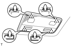
(a) Connect the connector.
(b) Attach the 4 clips to install the room light.
55. INSTALL ROOF CONSOLE BOX ASSEMBLY (w/ Rear Seat Entertainment System)

(a) Connect the connector.
(b) Attach the 4 clips and 2 claws to install the roof console box.
(c) Install the 2 bolts.
56. INSTALL NO. 1 ROOF LINING TRIM COVER (w/ Rear Seat Entertainment System)
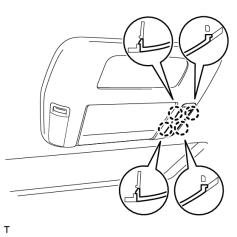
(a) Attach the 4 claws to install the cover.
57. INSTALL NO. 2 ROOF LINING TRIM COVER (w/ Rear Seat Entertainment System)
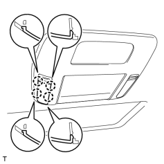
(a) Attach the 4 claws to install the cover.
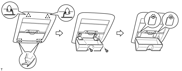
58. INSTALL MAP LIGHT ASSEMBLY
(a) Connect the 2 connectors.
(b) Attach the 2 clips and 2 guides to install the map light.
(c) Install the 2 screws.
(d) Attach the 2 claws to close the 2 covers.
59. INSTALL REAR UPPER PILLAR GARNISH LH
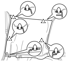
(a) Attach the 5 clips to install the rear upper pillar garnish.
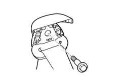
|
(b) Install the seat belt shoulder anchor with the bolt. Torque: 42 N·m (428 kgf·cm, 31 ft·lbf) |

|
(c) Attach the 2 claws to close the seat belt shoulder anchor cover. |
60. INSTALL REAR UPPER PILLAR GARNISH RH
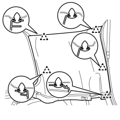
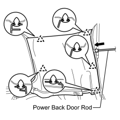
(a) w/o Power Back Door:
(1) Attach the 5 clips to install the rear upper pillar garnish.
|
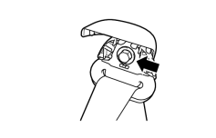
(b) w/ Power Back Door: (1) Pass the power back door rod through the rear upper pillar garnish. (2) Attach the 5 clips to install the rear upper pillar garnish. |
|
(c) Install the seat belt shoulder anchor with the bolt. Torque: 42 N·m (428 kgf·cm, 31 ft·lbf) |

|
(d) Attach the 2 claws to close the seat belt shoulder anchor cover. |
61. INSTALL BACK DOOR SERVICE HOLE COVER RH (w/ Power Back Door)
62. INSTALL BACK DOOR SIDE GARNISH RH (w/ Power Back Door)
63. INSTALL CENTER BACK DOOR GARNISH (w/ Power Back Door)
64. INSTALL REAR FRONT QUARTER TRIM GARNISH LH
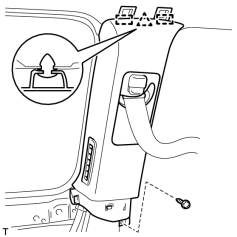
(a) Pass the seat belt anchor through the quarter trim garnish.
(b) Attach the clip and 2 guides to install the quarter trim garnish.
(c) Install the screw.
65. INSTALL REAR FRONT QUARTER TRIM GARNISH RH
HINT:
Use the same procedures described for the LH side.
66. INSTALL FRONT QUARTER TRIM PANEL ASSEMBLY LH
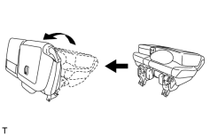
HINT:
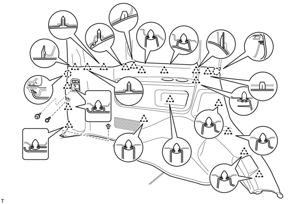
When installing the front quarter trim panel, operate the reclining adjuster release handle and move the No. 1 rear seat to the position shown in the illustration.
(a) for Rear No. 2 Seat with Manual Folding-up Function:
(1) Connect the thermistor connector, power outlet socket connector and rear seat lock control lever cable.
(2) Attach the 19 clips and 2 claws to install the quarter trim panel.
(3) Install the screw, clip and bolt.
Torque: 12 N·m (122 kgf·cm, 9 ft·lbf)
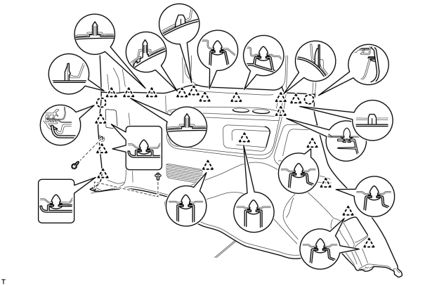
(b) for Rear No. 2 Seat with Automatic Folding-up Function:
(1) Connect the thermistor connector and power outlet socket connector.
(2) Attach the 19 clips and 2 claws to install the quarter trim panel.
(3) Install the screw and clip.
|
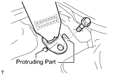
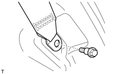
(c) Install the rear No. 2 seat belt anchor with the bolt. Torque: 42 N·m (428 kgf·cm, 31 ft·lbf) NOTICE:
Do not overlap the anchor part of the seat belt and protruding parts of the vehicle body. |
|
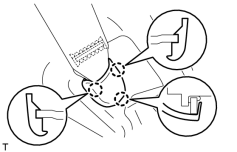
(d) Install the rear No. 1 seat belt anchor with the bolt. Torque: 42 N·m (428 kgf·cm, 31 ft·lbf) |
|
(e) Attach the 3 claws to install the cover. |
67. INSTALL FRONT QUARTER TRIM PANEL ASSEMBLY RH
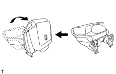
HINT:
When installing the front quarter trim panel, operate the reclining adjuster release handle and move the No. 1 rear seat to the position shown in the illustration.
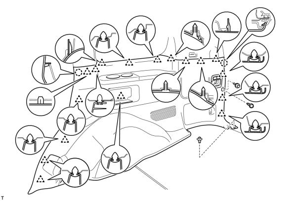
(a) for Rear No. 2 Seat with Manual Folding-up Function:
(1) Connect the thermistor connector and rear seat lock control lever cable.
(2) Attach the 17 clips and 2 claws to install the quarter trim panel.
(3) Install the screw, clip and bolt.
Torque: 12 N·m (122 kgf·cm, 9 ft·lbf)
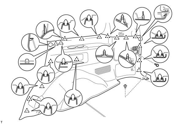
(b) for Rear No. 2 Seat with Automatic Folding-up Function:
(1) Connect the thermistor connector.
(2) Attach the 17 clips and 2 claws to install the quarter trim panel.
(3) Install the screw and clip.
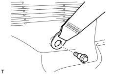
|
(c) Install the rear No. 2 seat belt anchor with the bolt. Torque: 42 N·m (428 kgf·cm, 31 ft·lbf) |
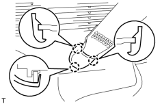
|
(d) Attach the 3 claws to install the cover. |
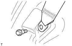
|
(e) Install the rear No. 1 seat belt anchor with the bolt. Torque: 42 N·m (428 kgf·cm, 31 ft·lbf) |
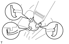
|
(f) Attach the 3 claws to install the cover. |
68. INSTALL REAR SEAT COVER CAP (for Rear No. 2 Seat with Manual Folding-up Function)
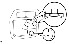
HINT:
Use the same procedures to install the rear seat cover cap on the other side.
(a) Attach the 3 claws to install the rear seat cover cap.
69. INSTALL NO. 1 LUGGAGE COMPARTMENT TRIM HOOK
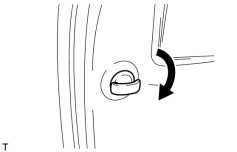
HINT:
Use the same procedure to install the luggage compartment trim hook on the other side.
(a) Install the luggage compartment trim hook by turning it clockwise.
70. INSTALL CENTER PILLAR GARNISH LH
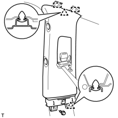
(a) Pass the seat belt anchor through the center pillar garnish.
(b) Attach the 2 clips and 2 guides to install the center pillar garnish.
(c) Install the bolt.
71. INSTALL CENTER PILLAR GARNISH RH
HINT:
Use the same procedures described for the LH side.
72. INSTALL REAR ASSIST GRIP ASSEMBLY
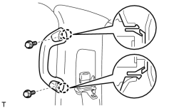
HINT:
Use the same procedure to install the rear assist grip on the other side.
(a) Attach the 2 claws to install the rear assist grip.
(b) Install the 2 bolts.
|
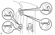
(c) Attach the 4 claws to install the 2 assist grip plugs. |
73. INSTALL CENTER LOWER PILLAR GARNISH LH
HINT:
- When installing the center lower pillar garnish, connect the cable to the negative (-) battery terminal and operate the power seat switch to move the front seat and seatback to the foremost upright position.
- After moving the front seat, disconnect the cable from the negative (-) battery terminal.
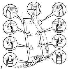
|
(a) Attach the 2 claws and 7 clips to install the center lower pillar garnish. |
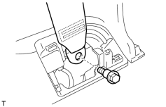
|
(b) Install the seat belt anchor with the bolt. Torque: 42 N·m (428 kgf·cm, 31 ft·lbf) |
74. INSTALL CENTER LOWER PILLAR GARNISH RH
HINT:
- When installing the center lower pillar garnish, connect the cable to the negative (-) battery terminal and operate the power seat switch to move the front seat and seatback to the foremost upright position.
- After moving the front seat, disconnect the cable from the negative (-) battery terminal.
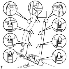
|
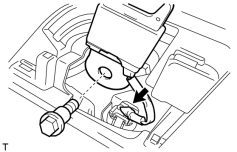
(a) Attach the 2 claws and 7 clips to install the center lower pillar garnish. |
|
(b) Install the seat belt anchor with the bolt. Torque: 42 N·m (428 kgf·cm, 31 ft·lbf) |
(c) Connect the connector.
75. INSTALL CENTER PILLAR GARNISH COVER LH
HINT:
- When installing the center pillar garnish cover, connect the cable to the negative (-) battery terminal and operate the power seat switch to move the front seat and seatback to the foremost upright position.
- After moving the front seat, disconnect the cable from the negative (-) battery terminal.
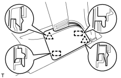
|
(a) Attach the 2 clips and 2 guides to install the cover. |
76. INSTALL CENTER PILLAR GARNISH COVER RH
HINT:
Use the same procedures described for the LH side.
77. INSTALL FRONT PILLAR GARNISH LH
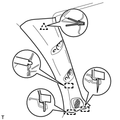
(a) Connect the speaker connector.
(b) Attach the clip and 3 guides to install the front pillar garnish.
78. INSTALL FRONT PILLAR GARNISH RH
HINT:
Use the same procedures described for the LH side.
79. INSTALL FRONT ASSIST GRIP SUB-ASSEMBLY
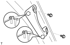
HINT:
Use the same procedure to install the front assist grip on the other side.
(a) Attach the 2 claws to install the front assist grip.
(b) Install the 2 bolts.
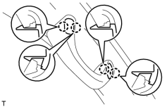
|
(c) Attach the 4 claws to install the 2 assist grip plugs. |
80. INSTALL REAR FLOOR MAT REAR SUPPORT PLATE
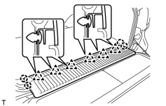
(a) Attach the 6 clips and 4 claws to install the support plate.
81. INSTALL REAR DOOR SCUFF PLATE LH
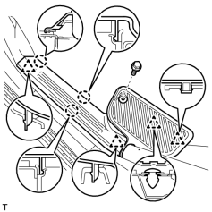
(a) w/o Illumination Type Front Door Scuff Plate:
(1) Attach the 3 claws and 4 clips to install the scuff plate.
(2) Install the screw.
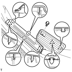
|
(b) w/ Illumination Type Front Door Scuff Plate: (1) Attach the 3 claws and 4 clips to install the scuff plate. (2) Install the screw. |
82. INSTALL REAR DOOR SCUFF PLATE RH
HINT:
Use the same procedures described for the LH side.
83. INSTALL REAR STEP COVER
HINT:
Use the same procedure to install the step cover on the other side.
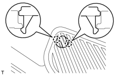
|
(a) w/o Illumination Type Front Door Scuff Plate: Attach the 2 claws to install the step cover. |
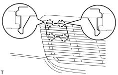
|
(b) w/ Illumination Type Front Door Scuff Plate: Attach the 4 claws to install the step cover. |
84. INSTALL FRONT DOOR SCUFF PLATE LH
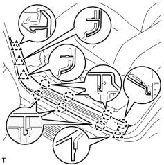
(a) w/o Illumination:
(1) Attach the 7 claws and 4 clips to install the scuff plate.
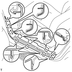
|
(b) w/ Illumination: (1) Connect the connector. (2) Attach the 7 claws and 4 clips to install the scuff plate. |
85. INSTALL FRONT DOOR SCUFF PLATE RH
HINT:
Use the same procedures described for the LH side.
86. INSTALL REAR NO. 2 SEAT ASSEMBLY LH
(a) w/ Manual Folding-up Function:
Install the rear No. 2 seat assembly LH
.
(b) w/ Automatic Folding-up Function:
Install the rear No. 2 seat assembly LH
.
87. INSTALL REAR NO. 2 SEAT ASSEMBLY RH
HINT:
Use the same procedures described for the LH side.
88. CONNECT CABLE TO NEGATIVE BATTERY TERMINAL
NOTICE:
When disconnecting the cable, some systems need to be initialized after the cable is reconnected
.
89. INSTALL ENGINE ROOM SIDE COVER LH

|

|