| Last Modified: 11-27-2007 | 1.6 A | |
| Service Category: Vehicle Exterior | Section: Door/Hatch | |
| Model Year: 2008 | Model: LX570 | Doc ID: RM000001BLH00GX |
| Title: DOOR / HATCH: BACK DOOR: REASSEMBLY (2008 LX570) | ||
REASSEMBLY
1. INSTALL BACK DOOR STAY ASSEMBLY LH

2. INSTALL BACK DOOR STAY ASSEMBLY RH
HINT:
Use the same procedures described for the LH side.
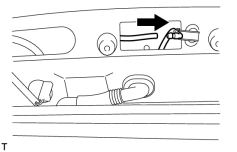
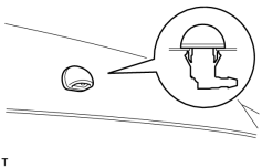
3. INSTALL REAR WASHER NOZZLE
|
(a) Connect the hose. |
|
(b) Attach the 2 claws to install the washer nozzle. |
4. INSTALL REAR SPOILER SUB-ASSEMBLY
5. INSTALL BACK DOOR GLASS CHANNEL LH (w/o Power Back Door)
6. INSTALL BACK DOOR GLASS CHANNEL RH (w/o Power Back Door)
7. INSTALL BACK DOOR GARNISH SUB-ASSEMBLY OUTSIDE
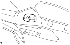
8. INSTALL LOWER BACK DOOR STOPPER
|
(a) Install the lower back door stopper with the bolt. |
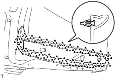
9. INSTALL LIFT GATE WEATHERSTRIP
|
(a) Attach the 25 clips to install the lift gate weatherstrip. NOTICE:
Do not pull strongly on the weatherstrip as it may be damaged. |
10. INSTALL REAR TELEVISION CAMERA ASSEMBLY
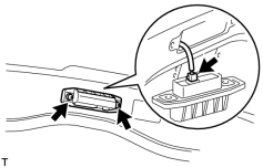
11. INSTALL BACK DOOR OPENER SWITCH ASSEMBLY
|
(a) Connect the connector and then install the back door opener switch. |
(b) Install the 2 screws.
Torque: 7.5 N·m (76 kgf·cm, 66 in·lbf)
12. INSTALL LICENSE PLATE LIGHT ASSEMBLY
13. INSTALL BACK DOOR GARNISH RETAINER SUB-ASSEMBLY
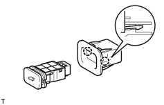
14. INSTALL BACK DOOR CONTROL SWITCH (w/ Power Back Door)
|
(a) Attach the 2 claws to install the door control switch. |
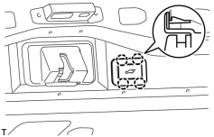
15. INSTALL SWITCH BEZEL (w/ Power Back Door)
|
(a) Attach the 4 claws to install the switch bezel. |
(b) Connect the connector.
16. INSTALL BACK DOOR LOCK PROTECTOR (w/ Power Back Door)
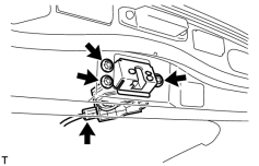
17. INSTALL BACK DOOR LOCK ASSEMBLY
(a) w/o Power Back Door:
|
(1) Install the back door lock with the 3 bolts. Torque: 13 N·m (133 kgf·cm, 10 ft·lbf) |
(2) Connect the connector.
(b) w/ Power Back Door:
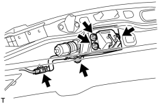
|
(1) Install the back door lock with the 4 bolts. Torque: 13 N·m (133 kgf·cm, 10 ft·lbf) |
(2) Connect the connector.
18. INSTALL BACK DOOR LOCK COVER
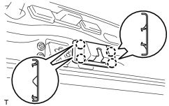
|
(a) Attach the 4 claws to install the back door lock cover. |
19. INSTALL REAR WIPER MOTOR ASSEMBLY
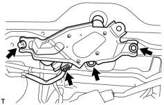
|
(a) Temporarily install the rear wiper motor assembly with the 3 bolts. |
(b) Tighten the 3 bolts.
Torque: 5.5 N·m (56 kgf·cm, 49 in·lbf)
(c) Connect the connector.
20. INSTALL REAR WIPER MOTOR GROMMET
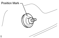
|
(a) Install the rear wiper motor grommet with the position mark facing upward as shown in the illustration. |
21. INSTALL REAR WIPER ARM
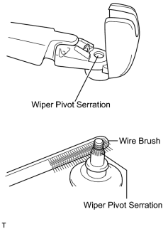
(a) Operate the rear wiper, and stop the rear wiper motor at the automatic stop position.
|
(b) Clean the wiper pivot serration with a wire brush. |
|
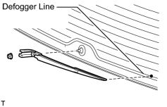
(c) Set the head of the blade on the defogger line. |
(d) Install the rear wiper arm with the nut.
Torque: 5.5 N·m (56 kgf·cm, 49 in·lbf)
(e) Close the cover.
22. INSTALL POWER BACK DOOR SENSOR ASSEMBLY LH (w/ Power Back Door)
|
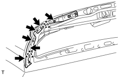
(a) Attach the 2 clips to Install the power back door sensor assembly LH. |
(b) Using a T25 "TORX" wrench, install the 6 screws.
|
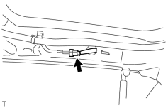
(c) Connect the connector. |
23. INSTALL POWER BACK DOOR SENSOR ASSEMBLY RH (w/ Power Back Door)
HINT:
Use the same procedures described for the LH side.
24. INSTALL REAR HEADER SPEAKER ASSEMBLY (for 19 Speakers)
25. INSTALL BACK DOOR GARNISH
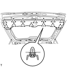
|
(a) Attach the 14 clips to install the back door garnish. |
26. INSTALL BACK DOOR SERVICE HOLE COVER RH (w/ Power Back Door)
(a) When reusing the power back door rod:
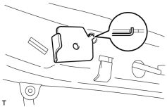
|
(1) Install the back door stay plate. |
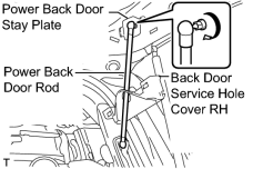
|
(2) Pass the power back door rod through the hole of the back door service hole cover and install the rod with the bolt. Torque: 18 N·m (184 kgf·cm, 13 ft·lbf) |
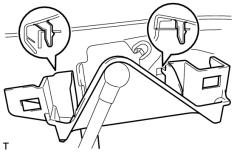
|
(3) Move the service hole cover and attach the 2 clips. |
(b) When installing a new power back door rod:
|
|
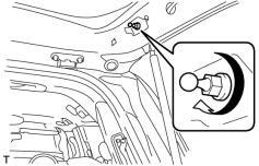
(1) Install the back door stay plate. |
|
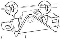
(2) Install the back door stay bolt. Torque: 18 N·m (184 kgf·cm, 13 ft·lbf) |
|
(3) Attach the 2 clips to install move the service hole cover. |
|
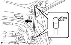
(4) Attach the ball joints to install the power back door rod. |
27. INSTALL BACK DOOR SIDE GARNISH LH
|
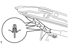
(a) Attach the 3 clips to install the back door side garnish. |
28. INSTALL BACK DOOR SIDE GARNISH RH
(a) w/o Power Back Door:
HINT:
Use the same procedures described for the LH side.
(b) w/ Power Back Door:
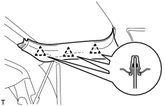
|
(1) Attach the 3 clips to install the back door side garnish. |
29. INSTALL CENTER STOP LIGHT ASSEMBLY
30. INSTALL CENTER BACK DOOR GARNISH
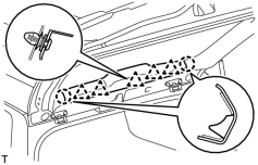
|
(a) Attach the 5 clips and 2 claws to install the back door garnish. |
31. INSTALL LOWER BACK DOOR STOPPER CUSHION
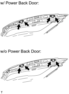
|
(a) Install the 2 back door stopper cushions with the 4 bolts. |
32. INSTALL BACK DOOR GRIP
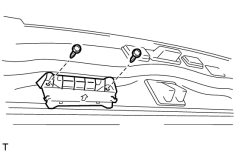
|
(a) Install the back door grip with the 2 screws. |
33. CONNECT CABLE TO NEGATIVE BATTERY TERMINAL
NOTICE:
When disconnecting the cable, some systems need to be initialized after the cable is reconnected
.
34. INSTALL ENGINE ROOM SIDE COVER LH

|

|