| Last Modified: 11-27-2007 | 1.6 A | |
| Service Category: Engine/Hybrid System | Section: Fuel System | |
| Model Year: 2008 | Model: LX570 | Doc ID: RM0000039W8009X |
| Title: 3UR-FE FUEL: FUEL TANK: INSTALLATION (2008 LX570) | ||
INSTALLATION
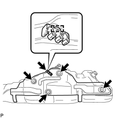
1. INSTALL NO. 1 FUEL TANK HEAT INSULATOR
|
(a) Install the No. 1 fuel tank heat insulator with the 4 clips. |
(b) Install the fuel tube clamp to the No. 1 fuel tank heat insulator.
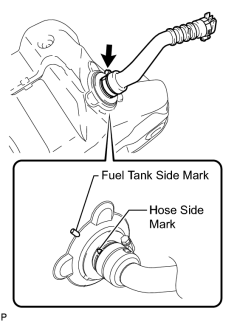
2. INSTALL FUEL TANK TO FILLER PIPE HOSE
|
(a) Install the fuel tank to filler pipe hose to the fuel tank as shown in the illustration. HINT:
|
3. INSTALL FUEL SUCTION WITH PUMP AND GAUGE TUBE ASSEMBLY

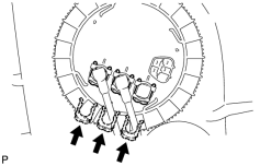
4. INSTALL FUEL TANK MAIN TUBE SUB-ASSEMBLY AND FUEL TANK RETURN TUBE SUB-ASSEMBLY
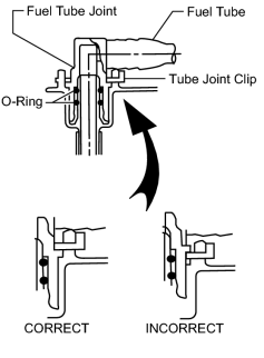
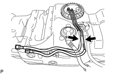
(a) Install the 2 fuel tank tubes and No. 1 fuel tube joint with the 3 tube joint clips.
NOTICE:
- Check that there are no scratches or foreign objects on the connecting parts.
- Check that the fuel tube joints are inserted securely.
- Check that the tube joint clips are on the collars of the fuel tube joints.
- After installing the tube joint clips, check that the fuel tube joints have not been pulled off.
|
(b) Install the fuel tank main tube and fuel tank return tube to the fuel tank. |
5. INSTALL FUEL TANK SUB-ASSEMBLY
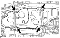
(a) Set the fuel tank on a transmission jack and raise the fuel tank.
(b) Raise the transmission jack.
|
(c) Install the 2 fuel tank bands with the 2 pins and 2 clips. |
(d) Connect the 2 fuel tank bands with the 2 bolts.
Torque: 40 N·m (408 kgf·cm, 30 ft·lbf)
6. CONNECT FUEL TANK TO FILLER PIPE HOSE
|
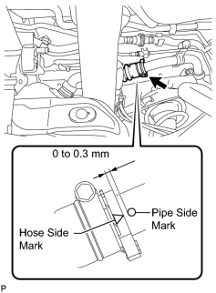
(a) Connect the fuel tank to filler pipe hose to the fuel tank filler pipe as shown in the illustration. HINT:
|
7. CONNECT FUEL TANK BREATHER TUBE SUB-ASSEMBLY
|
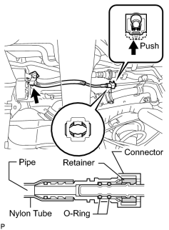
(a) Connect the fuel tank breather tube to the fuel tank filler pipe. HINT:
Push the parts together firmly until a "click" sound is heard. NOTICE:
|
(b) Attach the fuel tube clamp.
8. CONNECT NO. 2 FUEL TANK BREATHER TUBE SUB-ASSEMBLY
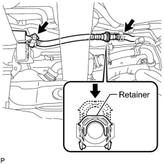
|
(a) Connect the fuel tank breather tube to the filler pipe and push the retainer. NOTICE:
|
(b) Attach the 2 fuel tube clamps.
9. CONNECT FUEL TANK RETURN TUBE SUB-ASSEMBLY
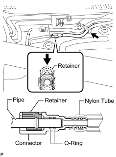
|
(a) Connect the fuel tank return tube and push the retainer. HINT:
Push the parts together firmly until a "click" sound is heard. NOTICE:
|
(b) Attach the fuel tube clamp.
10. CONNECT FUEL TANK MAIN TUBE SUB-ASSEMBLY
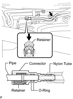
|
(a) Connect the fuel tank main tube and push the retainer. HINT:
Push the parts together firmly until a "click" sound is heard. NOTICE:
|
(b) Attach the fuel tube clamp.
11. INSTALL NO. 1 FUEL TANK PROTECTOR SUB-ASSEMBLY
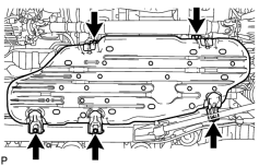
|
(a) Install the tank protector with the 5 bolts. Torque: 20 N·m (204 kgf·cm, 15 ft·lbf) |
12. INSTALL FUEL TANK CAP ASSEMBLY
13. INSTALL REAR FLOOR NO. 2 SERVICE HOLE COVER
|
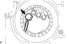
(a) Connect the fuel pump and fuel sender gauge connector. |
|
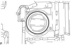
(b) Install the service hole cover with new butyl tape. |
|
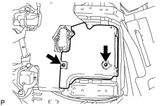
(c) Install the air duct with the 2 screws. |
14. INSTALL FRONT FLOOR CARPET ASSEMBLY
15. INSTALL REAR SEAT ASSEMBLY
(a) Install the rear No. 1 seat assembly and rear No. 2 seat assembly
.
16. CONNECT CABLE TO NEGATIVE BATTERY TERMINAL
NOTICE:
When disconnecting the cable, some systems need to be initialized after the cable is reconnected
.
17. ADD FUEL
18. INSPECT FOR FUEL LEAK
19. INSPECT REAR NO. 1 SEAT ASSEMBLY RH
20. INSPECT REAR NO. 1 SEAT ASSEMBLY LH

|

|