REMOVAL
Removal / installation
| 1. DISCONNECT CABLE FROM BATTERY NEGATIVE TERMINAL |

- NOTICE:
- Wait for 90 seconds after disconnecting the cable to prevent the airbag working.
| 2. REMOVE ABS MOTOR RELAY |
In order to prohibit brake control, remove the 2 ABS motor relays with the ignition switch off.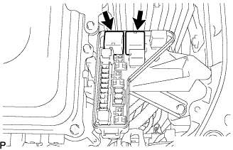

- NOTICE:
- If the pump motor operates while air remains inside the brake actuator hose, the air will enter the actuator, resulting in difficulty in bleeding the brakes.
| 3. REMOVE FRONT WIPER ARM RH |
Remove the 2 nuts and the front wiper arm and blade assembly RH.
| 4. REMOVE FRONT WIPER ARM LH |
Remove the nut and the front wiper arm and blade assembly LH.
| 5. REMOVE FRONT FENDER TO COWL SIDE SEAL RH |
| 6. REMOVE FRONT FENDER TO COWL SIDE SEAL LH |
| 7. REMOVE COWL TOP VENTILATOR LOUVER SUB-ASSEMBLY |
Remove the 2 clips.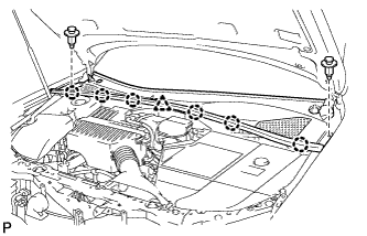
Disengage the 6 claws and the clamp, and remove the cowl top ventilator louver sub-assembly.
| 8. REMOVE WINDSHIELD WIPER MOTOR AND LINK ASSEMBLY |
Disconnect the connector.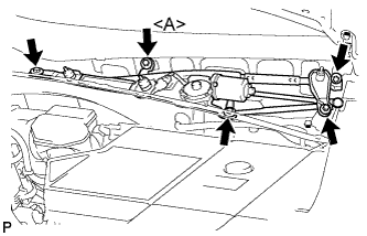
Remove the 5 bolts and the windshield wiper motor and link assembly.
- HINT:
- Bolt <A> cannot be removed because it is integrated into windshield wiper link assembly.
| 9. REMOVE COWL TOP PANEL SUB-ASSEMBLY OUTER |
Separate the wire harness clamp and grommet (A).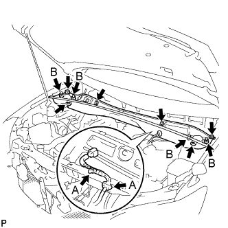
Remove the 4 shock absorber nuts (B).
Remove the 4 bolts, 2 nuts and cowl top panel sub-assembly.
Install the 4 shock absorber nuts.
- Torque:
- 80 N*m{ 815 kgf*cm , 59 ft.*lbf }
| 10. REMOVE BRAKE MASTER CYLINDER RESERVOIR ASSEMBLY (RHD) |
Disconnect the warning switch connector.
Separate the brake actuator hose from the clamp.
Remove the 2 clips and brake actuator hose.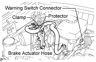
Remove the 2 clips and 2 reservoir tubes from the brake master cylinder reservoir assembly.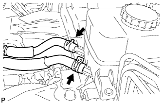
Remove the 2 bolts and the brake master cylinder reservoir assembly.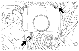
| 11. REMOVE RESERVOIR TUBE NO.1 |
LHD:
Remove the nut.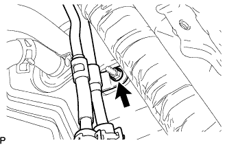
Remove the clip, and separate the reservoir tube No.1.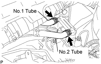
RHD:
Remove the clip, and separate the reservoir tube No.1.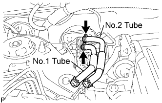
| 12. REMOVE RESERVOIR TUBE NO.2 |
Remove the clip, and separate the reservoir tube No.2.
| 13. REMOVE FRONT DOOR SCUFF PLATE LH (LHD) |
Disengage the 6 claws and 4 clips, and remove the front door scuff plate.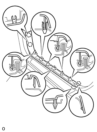
Disconnect the connector. (w/ illumination scuff plate)
| 14. REMOVE FRONT DOOR SCUFF PLATE RH (RHD) |
| 15. REMOVE COWL SIDE TRIM ASSEMBLY LH (LHD) |
Remove the 2 clips and the cowl side trim sub-assembly LH.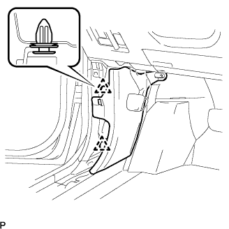
| 16. REMOVE COWL SIDE TRIM ASSEMBLY RH (RHD) |
| 17. REMOVE INSTRUMENT PANEL FINISH PANEL SUB-ASSEMBLY LOWER |
Using a screwdriver, open the instrument panel finish panel sub-assembly lower cover.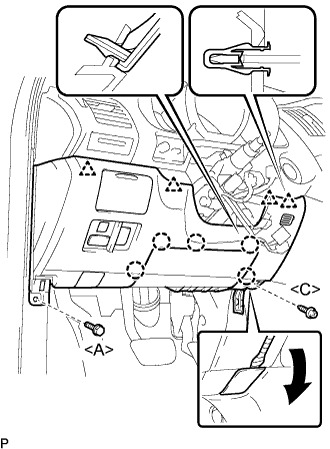
- HINT:
- Tape the screwdriver tip before use.
Remove the bolt <A> and the screw <C>.
Disconnect the hood lock control cable assembly.
Disengage the 5 claws and the 4 clips.
Disconnect the connectors and then remove the instrument panel finish panel sub-assembly lower.
| 18. REMOVE DRIVER SIDE KNEE AIRBAG ASSEMBLY |
Disconnect the connector from the driver side knee airbag assembly.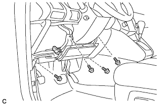
- NOTICE:
- When handling the airbag connector, take care not to damage the airbag wire harness.
Remove the 4 bolts and the driver side knee airbag assembly.
| 19. REMOVE BRAKE PEDAL RETURN SPRING |
| 20. SEPARATE MASTER CYLINDER PUSH ROD CLEVIS |
Remove the clip and clevis pin and disconnect the push rod clevis from the brake pedal.
| 21. REMOVE BRAKE MASTER CYLINDER W/SIMULATOR ASSEMBLY (LHD) |
Using SST, disconnect the 2 brake tubes.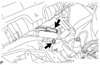
- SST
- 09023-00101
Disconnect the connector, and separate the wire harness clamp.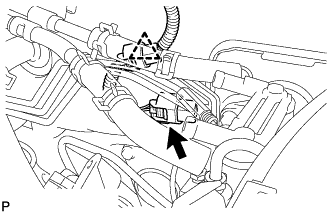
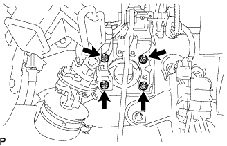
Remove the 4 nuts, the gasket and the brake master cylinder with simulator.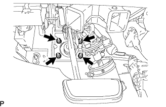
| 22. REMOVE BRAKE MASTER CYLINDER W/SIMULATOR ASSEMBLY (RHD) |
Using SST, disconnect the 2 brake tubes.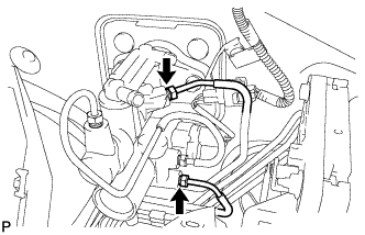
- SST
- 09023-00101
Disconnect the connector, and separate the wire harness clamp.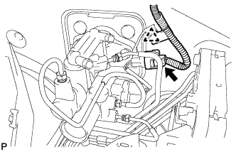
Remove the 4 nuts, the gasket and the brake master cylinder with simulator.