Front Wiper Motor Circuit
Circuit diagnosis
DESCRIPTION
The windshield wiper relay assembly controls the front wiper motor.Even if the windshield wiper relay assembly is in failure, its circuit structure enables operation of the front wiper.
WIRING DIAGRAM
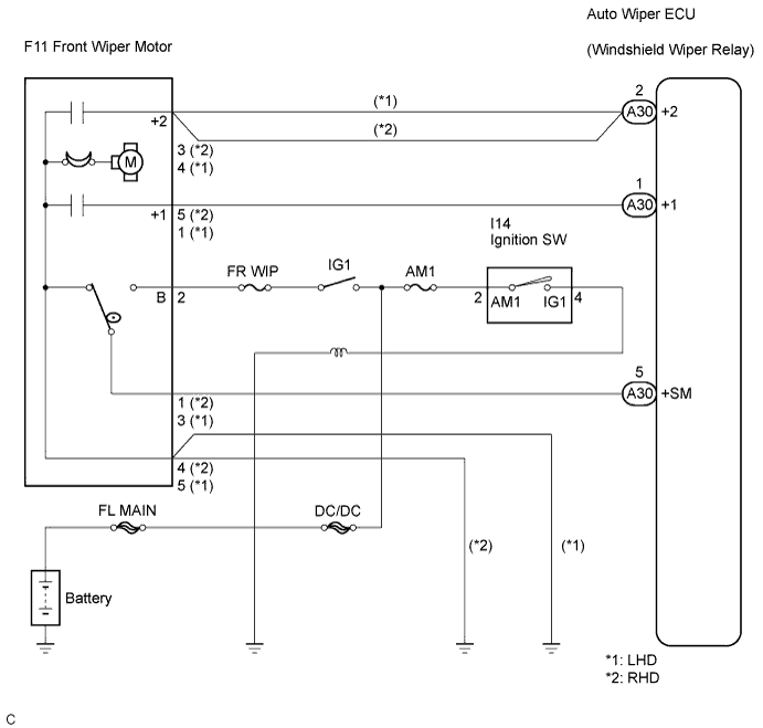

INSPECTION PROCEDURE
- HINT:
- Start the inspection from step 1 when using the intelligent tester, and start from step 2 when not using the intelligent tester.
| 1. PERFORM ACTIVE TEST BY INTELLIGENT TESTER |

Connect the intelligent tester to the DLC3.
Turn the ignition switch to the ON position and turn the intelligent tester's main switch ON.
Select the item below in the ACTIVE TEST and then check that the relay operates.
Wiper: Item
Test Details
Diagnostic Note
WIPER MOT (HI)
Front wiper motor HI operation ON / OFF
-
WIPER MOT (LO)
Front wiper motor LO operation ON / OFF
-
|
|
||||

| OK | ||
 |
||
| ||
| 2. INSPECT FUSE |
Inspect the AM1, FR WIP and INP J/B fuses.
Measure the resistance between each terminal.
- Standard resistance:
- Below 1 Ω
|
|
||||

| OK | |
 |
| 3. INSPECT WINDSHIELD WIPER RELAY ASSEMBLY |
Measure the voltage according to the value(s) in the table below.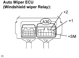
- Standard voltage:
Tester Connection
Condition
Specified Condition
+1 - Body ground
Ignition switch ON, Windshield wiper switch OFF → LO
Below 1 V → 10 to 14 V
+2 - Body ground
Ignition switch ON, Windshield wiper switch OFF → HI
Below 1 V → 10 to 14 V
+SM - Body ground
Ignition switch ON, Windshield wiper in automatic stop position → any position other than automatic stop position
Below 1 V → 10 to 14 V
|
|
||||
| OK | ||
|
||
| ||
| 4. INSPECT WINDSHIELD WIPER MOTOR ASSEMBLY |
Inspect the windshield wiper motor assembly (Click here).
|
|
||||
| OK | ||
|
||
| ||