REMOVAL
Removal / installation
| 1. DISCONNECT CABLE FROM BATTERY NEGATIVE TERMINAL |

- NOTICE:
- Wait for 90 seconds after disconnecting the cable to prevent the airbag working.
| 2. REMOVE INSTRUMENT CLUSTER FINISH PANEL SUB-ASSEMBLY |
Disengage the 4 clips and remove the instrument cluster finish panel sub-assembly.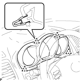

| 3. REMOVE COMBINATION METER ASSEMBLY |
Remove the 4 screws.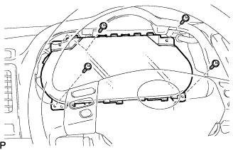
Pull out the combination meter assembly, and disconnect the connectors.
| 4. REMOVE FRONT DOOR SCUFF PLATE LH (LHD) |
Disengage the 6 claws and 4 clips, and remove the front door scuff plate.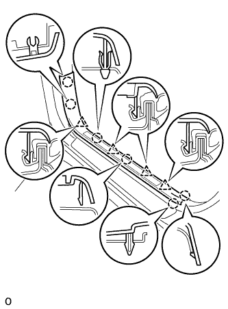
Disconnect the connector. (w/ illumination scuff plate)
| 5. REMOVE FRONT DOOR SCUFF PLATE RH (RHD) |
| 6. REMOVE COWL SIDE TRIM ASSEMBLY LH (LHD) |
Remove the 2 clips and the cowl side trim sub-assembly LH.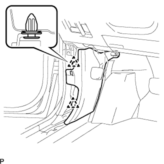
| 7. REMOVE COWL SIDE TRIM ASSEMBLY RH (RHD) |
| 8. REMOVE INSTRUMENT PANEL FINISH PANEL SUB-ASSEMBLY LOWER |
Using a screwdriver, open the instrument panel finish panel sub-assembly lower cover.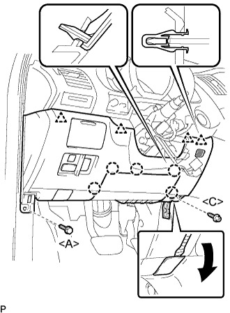
- HINT:
- Tape the screwdriver tip before use.
Remove the bolt <A> and the screw <C>.
Disconnect the hood lock control cable assembly.
Disengage the 5 claws and the 4 clips.
Disconnect the connectors and then remove the instrument panel finish panel sub-assembly lower.
| 9. REMOVE DRIVER SIDE KNEE AIRBAG ASSEMBLY |
Disconnect the connector from the driver side knee airbag assembly.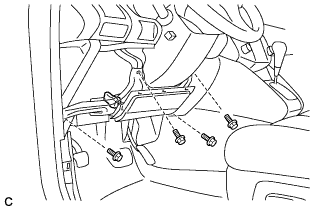
- NOTICE:
- When handling the airbag connector, take care not to damage the airbag wire harness.
Remove the 4 bolts and the driver side knee airbag assembly.
| 10. REMOVE BRAKE PEDAL RETURN SPRING |
| 11. SEPARATE MASTER CYLINDER PUSH ROD CLEVIS |
Remove the clip and clevis pin and disconnect the push rod clevis from the brake pedal.
| 12. REMOVE BRAKE PEDAL ASSEMBLY |
Disconnect the connector from the stop light switch.
Disconnect the connector from the pedal stroke sensor.
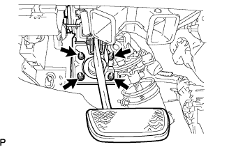
Remove the bolt.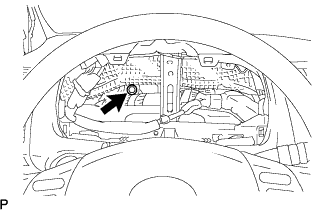
Remove the 4 nuts and the brake pedal support assembly.